
Component family
Ceramic Nozzles
Nozzles in ceramic for abrasive media, molten metal, high temperature and chemically aggressive flow, in duties where a metal nozzle erodes or degrades in service.
- Throat diameter held
- Profile accuracy
- Inlet-outlet concentricity
- Outlet edge condition
A ceramic nozzle is a flow-control component with a machined internal profile – throat, convergent and divergent sections – produced in a material that survives abrasive media, molten metal or high temperature. Ceramic is chosen for duties in which a metal nozzle erodes or degrades. What the machining controls is geometry: throat diameter, profile form, concentricity and edge condition. Flow performance in service follows from that geometry, but it is verified in the application, not by the dimensional inspection report.
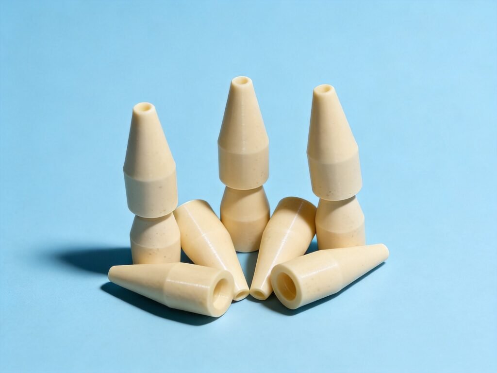
Machined ceramic nozzles in silicon carbide, alumina, boron nitride and silicon nitride — bores, profiles and outlet edges finished to the drawing.
Critical features
What this geometry is judged on
Each row ties one feature to why it matters, where it is at risk in manufacture, and how it is verified. The confirmed figures for these features sit further down the page, tied to the feature they were measured on.
Throat diameter
The controlling dimension. Flow follows from it, so it is ground and measured as a feature of its own.
Convergent and divergent profile
Ground as a form and then checked against the drawing, not assumed from the tool path.
Internal surface roughness
Specified on the flow path, because finish and throat diameter act together on the result.
Outlet edge
The edge criterion is agreed rather than left open. A chipped outlet changes the spray pattern.
Mounting features
Threaded, flanged or press-fit, ground so the nozzle seats concentric to the bore.
Multi-orifice and slotted outlets
Produced while the geometry is fine and finished after firing.
| Feature | Why it matters | Manufacturing risk | Inspection method |
|---|---|---|---|
| Throat diameter | The controlling dimension for flow | Producing an accurate throat in a very hard material | Optical or bore-gauge measurement of the throat |
| Profile form | Sets how the media accelerates | Grinding an internal form that resists direct probing | Optical comparison on a section or a replica |
| Bore concentricity | Keeps the spray on axis | Holding inlet-throat-outlet alignment | CMM on the end features |
| Internal finish | Acts with the throat on the result | Measuring roughness inside a small bore | Profilometer where access allows, otherwise process control |
| Outlet edge condition | A chipped edge changes the spray | Preventing chipping at the outlet | Optical inspection against the agreed criterion |
Possible ceramic materials
Material options and the reason behind each
The material is chosen from the dominant requirement. Where two requirements conflict, the trade-off is explained before quoting.
Suited to abrasive media and elevated temperature; the grade is chosen from the duty
Silicon carbide page →Process routes
How these parts are actually made
The route is chosen from the geometry and the tolerance, not from the material alone. It is stated with the quotation so the price can be read against the method.
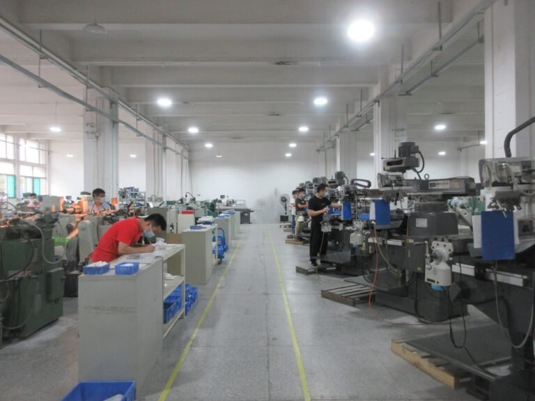
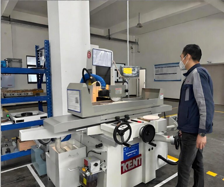
Bore and orifice machining
The orifice is the functional feature, so its diameter, roundness and edge condition are agreed as the governing callout.
Edge preparation
Ceramic has no ductility, so the entry and exit edges of an orifice are chamfered or radiused by agreement to prevent chipping.
Flow-related inspection
Orifice diameter and roundness are measured; the edge condition is checked optically rather than assumed from the dimensional result.
Where the difficulty sits
- Producing an accurate throat profile in a very hard material
- Controlling the internal surface finish, which drives flow
- Holding concentricity between the inlet bore, throat and outlet
- Grinding an internal taper that cannot be inspected easily
- Preventing chipping at the outlet edge
LimitBrittle material fails differently from metal. A feature that is merely difficult in steel can be impossible in ceramic, and the review states which of the two applies.
Confirmed capability
Customizable geometry and precision capability
Everything below is produced from the customer drawing. The figures are what the shop is confirmed to hold on the features this family carries, not a general tolerance for the whole part.
| Feature | Confirmed | Applies to |
|---|---|---|
| Hole diameter tolerance | 0.003 mm | Throat and bore diameters |
| Roundness | 0.0005 mm | Bores and cylindrical mounting features |
| Surface roughness | Ra 0.02 µm | Internal flow path and throat |
| Minimum slot width | 0.2 mm | Slotted and multi-orifice outlets |
Capabilities depend on material, geometry, feature size and finishing requirements. Critical dimensions are reviewed against the drawing.
| Measurement requirement | How it is verified |
|---|---|
| Throat diameter tolerance | Optical or video measurement of the throat; a bore gauge where access allows |
| Profile accuracy through the convergent section | Optical comparison against the drawing on a section or a replica, because the internal form cannot be probed directly |
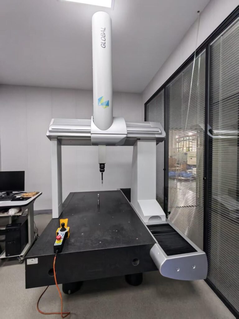
| Concentricity between inlet and outlet bores | CMM on the end features that carry the flow axis |
| Internal surface roughness on the flow path | Stylus profilometer where the bore allows access; smaller throats are backed by process control |
| Outlet edge condition | Optical inspection against the edge criterion agreed before machining |
Procurement risks
What goes wrong, and where it is avoided
Dimensional inspection verifies geometry, not flow performance; spray pattern and flow rate are verified in the application.
An outlet edge left unchamfered chips in service and changes the spray; the edge criterion belongs on the drawing.
A throat toleranced tighter than the media requires pays for measurement, not performance.
Internal profiles that cannot be inspected directly are verified on a section or a replica; the method is agreed at review.
Applications
Where the family is used
Component examples only. No customer names are published.
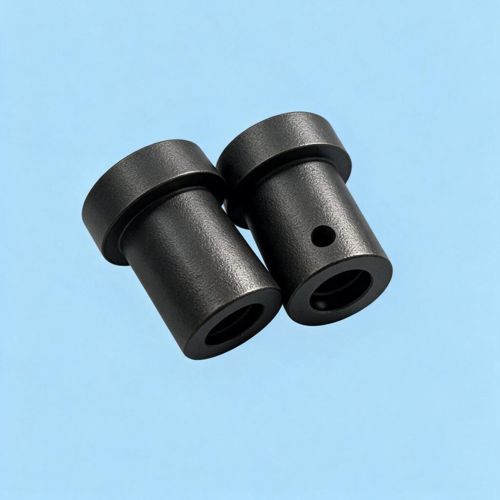
Abrasive blasting and shot peening
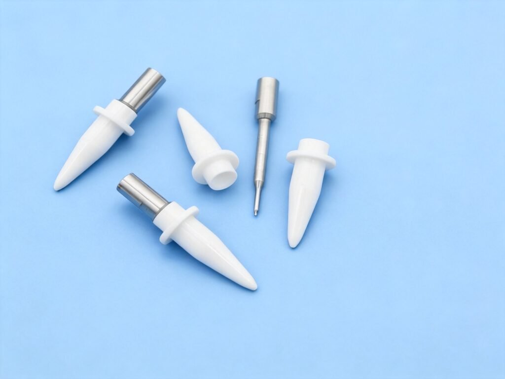
Molten metal transfer and die casting
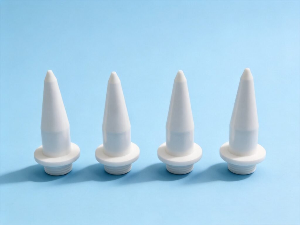
Combustion and burner hardware
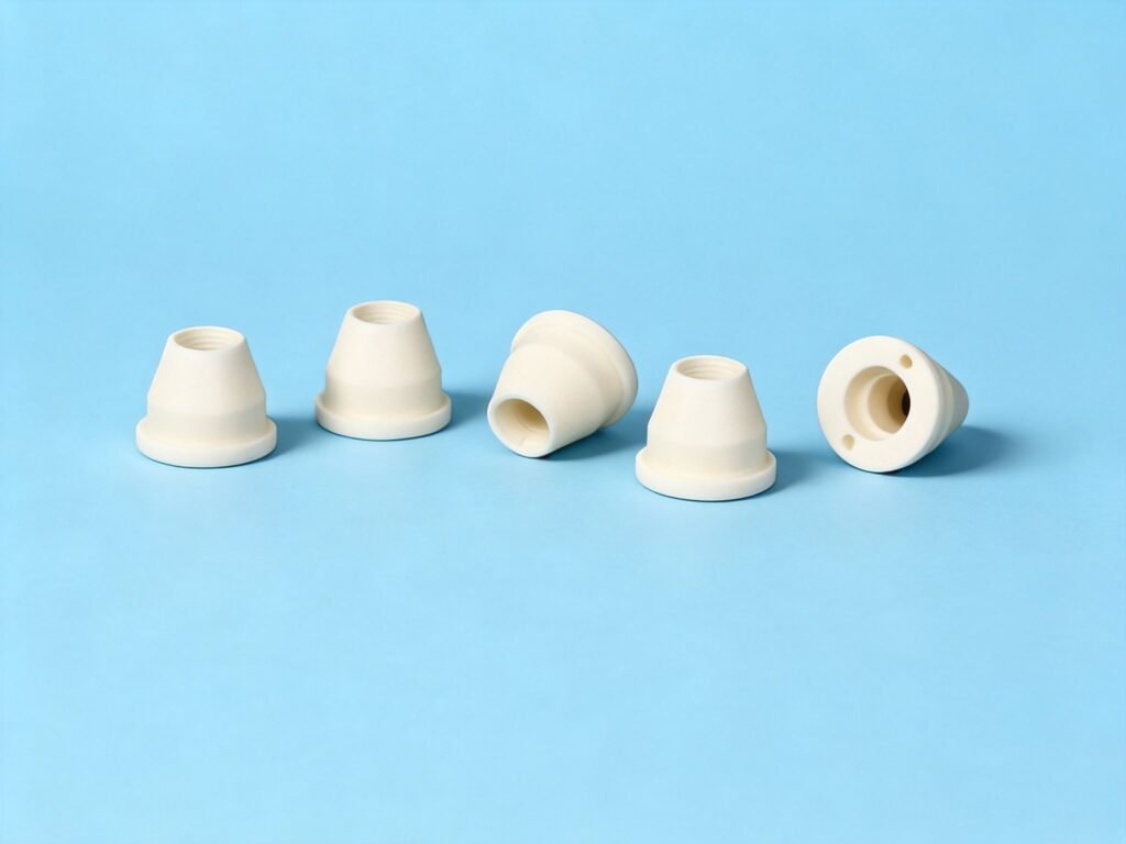
Water jet and high-pressure flow control
- Spray drying and coating systems
- Abrasive blast and sandblast nozzles
- High-temperature burner and combustion nozzles
- Flow-control orifices and metering jets
- Water-jet and cutting head nozzles
- Spray-drying and atomiser nozzles
- Welding and plasma torch nozzles
Engineering FAQ
Frequently asked
How do I specify the throat?
Give the throat diameter with its tolerance and the profile either as a drawing section or as a table of diameters along the axis. The profile is what controls flow, not just the throat.
Can the nozzle be relapped after service?
Some nozzles can be reworked if material was left for it. State at order stage that rework is intended so the initial dimensions allow for it.
Request a quote
Have a Ceramic Nozzle Drawing?
Geometry, material, quantity and the dimensions that matter. You get an engineering review before any price is given. Supplying the items below with the drawing removes the most common cause of a revised quotation.
- Full profile with the throat diameter toleranced
- Concentricity requirement between inlet and outlet
- Internal surface finish, and whether it applies to the throat only
- Mounting geometry: thread, flange or press fit
- The media and duty, so the material grade is chosen from the service and not assumed
| Type | Form |
|---|---|
| Convergent, divergent and venturi profiles | to the drawing |
| Straight-bore and stepped-bore nozzles | ground bores |
| Threaded, flanged or press-fit mounting | as required |
| Multi-orifice and slotted outlet geometry | per the drawing |
| Nozzles with a hardened or polished throat | where specified |