Industry
Optical and Photonics: Custom Ceramic Components
Precision components for optical assemblies, fibre systems and photonics equipment, where dimensional stability and surface quality decide the optical result.
Direct answer
What ceramic components does this industry use?
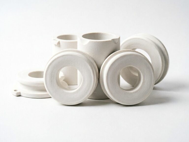
Optical and photonics equipment uses precision ceramic parts where alignment has to hold over temperature and service life: ferrules and alignment sleeves, reference and spacer plates, structural parts with fine datum control, and insulating components for active optical modules. Zirconia is the standard material for fibre ferrules; alumina serves reference and insulating parts; silicon carbide and silicon nitride carry structural duty where stiffness and thermal stability govern. Bore geometry, concentricity and surface condition decide the optical result, and they are judged from the drawing.
Where the parts sit, and what each one does
Each row ties an equipment class to the ceramic component used in it, the function the part performs, the candidate material, the feature that carries the risk and how that feature is verified. Materials named here are the ones described under material selection below.
| Equipment | Ceramic component | Function | Candidate material | Critical feature | Inspection |
|---|---|---|---|---|---|
| Fibre optic connectors and ferrules | Ferrules, alignment sleeves, split sleeves | Stable, wear-resistant alignment of the fibre | Zirconia (ZrO2) as the standard ferrule material | Bore diameter and its tolerance; bore entry geometry | Bore gauge and CMM; optical inspection of the bore entry |
| Optical benches and mounts | Reference plates, spacers, mounting structures | A reference geometry that holds position over temperature | Alumina (Al2O3); silicon nitride (Si3N4) where the part carries load | Flatness; position of datum features | CMM against the datum scheme |
| Interferometry and metrology | Reference surfaces, stable structural parts | A reference that does not drift with temperature | Silicon carbide (SiC) where stiffness and thermal stability govern | Flatness and surface finish of the reference face | Surface plate or CMM; surface roughness measurement |
| Laser systems | Insulating and structural components near optical paths | Isolation and support without contamination near the path | Alumina (Al2O3); silicon nitride (Si3N4) for structural parts | Edge quality near apertures; cleanliness of the parts | Optical edge inspection; cleaning as a specified process step |
| Optical communication modules | Alignment parts, ferrules, insulating housings | Repeatable mating over a long service life | Zirconia (ZrO2); alumina (Al2O3) for insulating housings | Concentricity between bore and outer diameter | Concentricity verification at small diameters |
What these parts are judged on
Each row ties one feature to why it matters in service, where it is at risk during manufacture, and how it is measured. The inspection plan is agreed before machining, because a ground ceramic dimension cannot be corrected afterwards.
| Feature | Why it matters | Manufacturing risk | Inspection method |
|---|---|---|---|
| Bore diameter and its tolerance | It decides insertion and alignment | Tight tolerances at small diameters, where handling rather than machine capability is the limiting factor | Bore gauge and CMM |
| Concentricity of bore to outer diameter | Misalignment shows up as insertion loss and wear | Holding concentricity between bore and outer diameter at small sizes | Concentricity verification at small diameters |
| Bore surface finish | It drives insertion loss and wear over repeated mating | Achieving a fine bore finish while keeping the bore entry intact | Surface roughness inside the bore where measurable |
| Bore entry geometry and edge condition | The entry is where insertion damage occurs | A chip near an aperture changes the optical result, not just the appearance of the part | Optical edge inspection for chips at the entry chamfer |
| Datum control on structural parts | Optical alignment depends on feature position holding over temperature | Datum transfer between grinding setups loses position | CMM against the datum scheme |
What the process demands of the material
The conditions below act on the part in service. Each one narrows the material or the geometry, and stating them is what turns the material choice into an engineering decision rather than a preference.
Dimensional stability
Feature positions have to hold over the operating temperature, or the optical path drifts and the assembly is re-aligned.
Surface finish
Ra on the functional face decides scatter, and where a bond follows, bond quality as well.
Flatness
Flatness over the functional area sets how the part seats against the next element in the stack.
Edge quality
A chip near an aperture or a window changes the optical result, not just the appearance of the part.
Thermal load
Where the assembly carries power, heat removal and alignment stop being separate problems.
Cleanliness
Residue from grinding is unacceptable on a surface that sits in the optical path, so cleaning is part of the specification.
Which materials suit this industry, and the limits
The material is chosen from the dominant requirement. Where two requirements conflict, the trade-off is explained before quoting rather than resolved silently.
| Material | Why it is chosen here |
|---|---|
| Zirconia (ZrO2) | The standard material for fibre ferrules: fine surface finish with high strength at small diameters |
| Alumina (Al2O3) | Reference and insulating components, and precision sleeves |
| Silicon carbide (SiC) | Stiff structural parts requiring thermal stability |
| Silicon nitride (Si3N4) | Structural optical bench components under load |
What is controlled and how it is verified
Dimensions and inspection method are agreed before machining, because ceramic cannot be reworked the way metal can.
Dimensions that usually matter
- Bore diameter and its tolerance on ferrules and sleeves
- Concentricity between bore and outer diameter
- Bore surface finish, which drives insertion loss and wear
- Bore entry geometry, including any chamfer
- Length and end face perpendicularity
Inspection applied
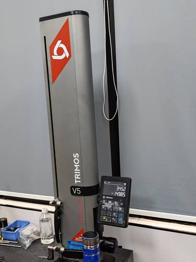
- Bore diameter by bore gauge and CMM
- Concentricity verification at small diameters
- Surface roughness inside the bore where measurable
- Optical and video inspection of the bore entry
- Optical edge inspection for chips at the entry chamfer
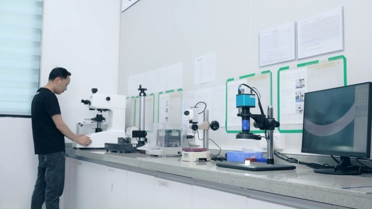
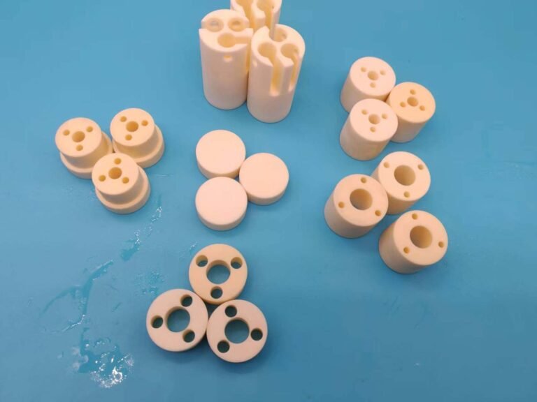
Parts made here, on our own equipment
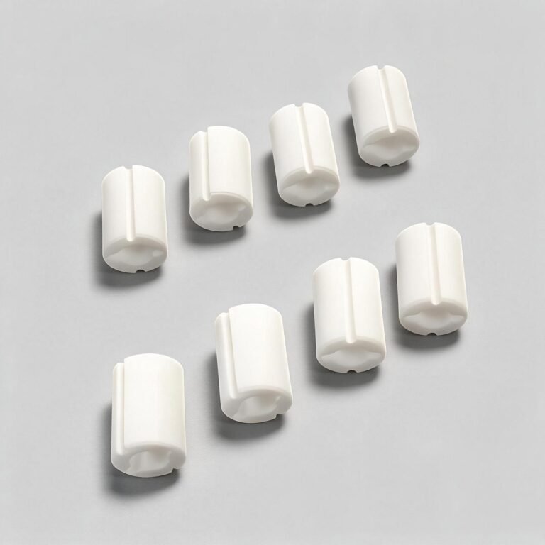
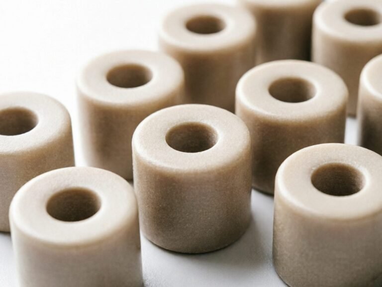
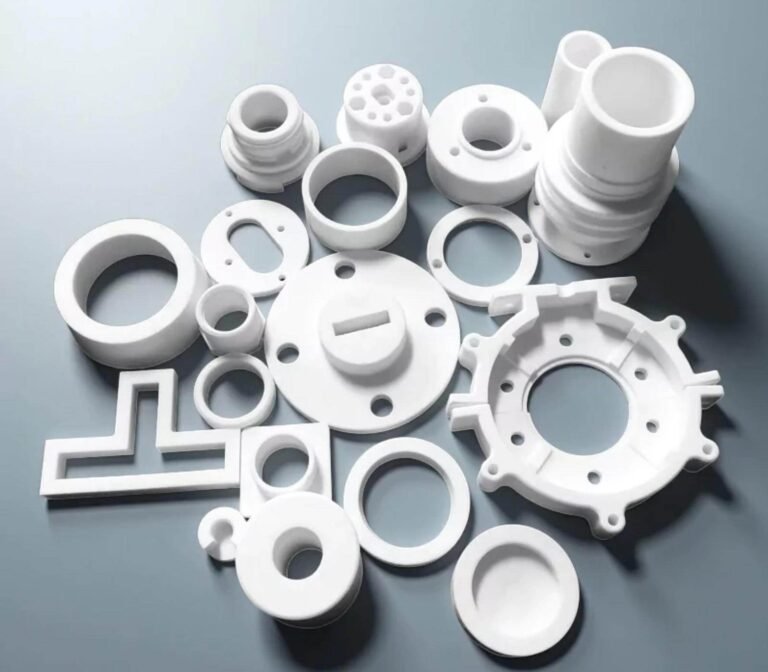
Component photographs are of parts produced in this factory. Equipment photographs are of this plant. No stock photography of facilities we do not own appears on this site.
What to send with a drawing
The review confirms material, route and inspection method from these inputs. Sending them with the drawing is what makes the first quotation accurate.
- Drawing or 3D model with the datum scheme and the optical interface defined
- Material or grade if already specified; otherwise the alignment function and the mating parts
- Bore, concentricity and edge requirements, with the chamfer geometry stated
- Quantity at each stage: evaluation, pilot and production
- Surface finish on functional faces and inside bores
- Inspection and documentation needs, including how bore finish is to be verified
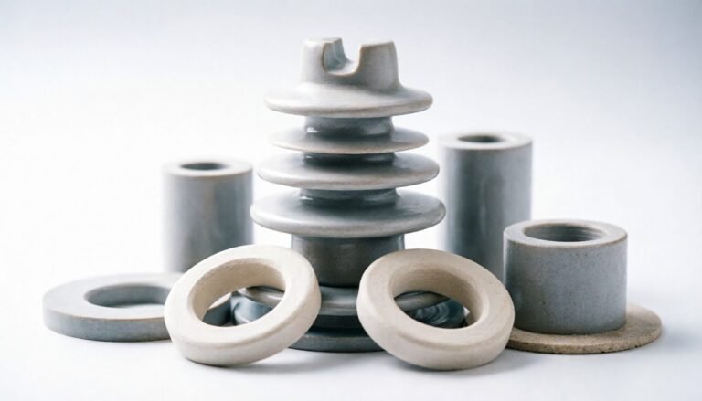
Parts from the batch
Frequently asked
Why is zirconia used for ferrules?
It combines high strength at small diameters with a fine surface finish, which is what the bore of a fibre ferrule needs. Its wear resistance also keeps the bore stable over repeated mating.
Can the bore entry be chamfered?
Yes, and it usually is. The chamfer geometry and its edge quality should be stated, because the entry is where insertion damage occurs.
How is a bore surface finish verified?
By surface roughness measurement where the geometry allows, combined with optical inspection. The method is agreed because it defines what the report can show.
Send a drawing for this industry
State the equipment, the operating conditions and the quantities. The review confirms material and route before quoting. Initial engineering feedback is returned within 2 business hours during published business hours (Mon-Fri 9:00-18:00 GMT+8), excluding Chinese statutory holidays and company-announced non-working days; this is initial feedback on the drawing, not completion of a formal quotation or a full engineering review.