
Component family
Ceramic Bushings
Bushings and bearing sleeves in ceramic, used in applications where wear, corrosion or electrical isolation can make ceramic preferable to conventional metallic bushings.
- Ground bores and outside diameters
- Bore-to-OD concentricity
- Flanged and shouldered forms
- Oil grooves and relief slots
A ceramic bushing is a plain bearing or guide sleeve with a ground bore and a ground outside diameter, used in applications where wear, corrosion or electrical isolation can make ceramic preferable to a conventional metallic bushing. The bore is the functional feature: it is ground, and lapped where a shaft runs in it. The engineering difficulty is holding the bore round and concentric with the outside diameter in a thin wall, because every error in that concentricity shows up as runout in service.
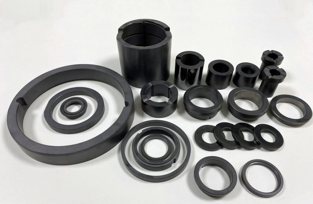
Machined ceramic bushings and sleeve bearings in alumina, zirconia, silicon nitride and silicon carbide — bores, walls and end faces finished to the drawing.
Critical features
What this geometry is judged on
Each row ties one feature to why it matters, where it is at risk in manufacture, and how it is verified. The confirmed figures for these features sit further down the page, tied to the feature they were measured on.
Bore
Ground, and lapped where a shaft runs in it.
Outside diameter
Ground concentric to the bore rather than to itself.
Wall thickness
Thin-wall bushings are where roundness is hardest to hold after firing.
Oil grooves, slots and reliefs
Produced so the bore keeps its roundness across the interruption.
End faces
Ground square to the bore axis, because they seat against a shoulder.
Tapered and split forms
Produced where the bushing is a fit or a clamp rather than a plain bearing.
| Feature | Why it matters | Manufacturing risk | Inspection method |
|---|---|---|---|
| Bore diameter and roundness | The shaft runs in it | Roundness in a short, stiff section | Bore gauge with a roundness check behind it |
| Bore-to-OD concentricity | Eccentricity shows up as runout | Holding wall thickness concentric around a small bore | Rotation on centres or CMM in a single setup |
| Wall thickness uniformity | The thin wall is the fit or the insulation | Machining grooves without losing roundness | Ball micrometer or ultrasonic spot checks |
| End-face squareness | Seats against a shoulder | Grinding faces square to the bore axis | CMM or surface plate with square and indicator |
| Bore finish | The bearing fit depends on it | Controlling finish inside a bore | Profilometer where bore access allows |
Possible ceramic materials
Material options and the reason behind each
The material is chosen from the dominant requirement. Where two requirements conflict, the trade-off is explained before quoting.
Process routes
How these parts are actually made
The route is chosen from the geometry and the tolerance, not from the material alone. It is stated with the quotation so the price can be read against the method.
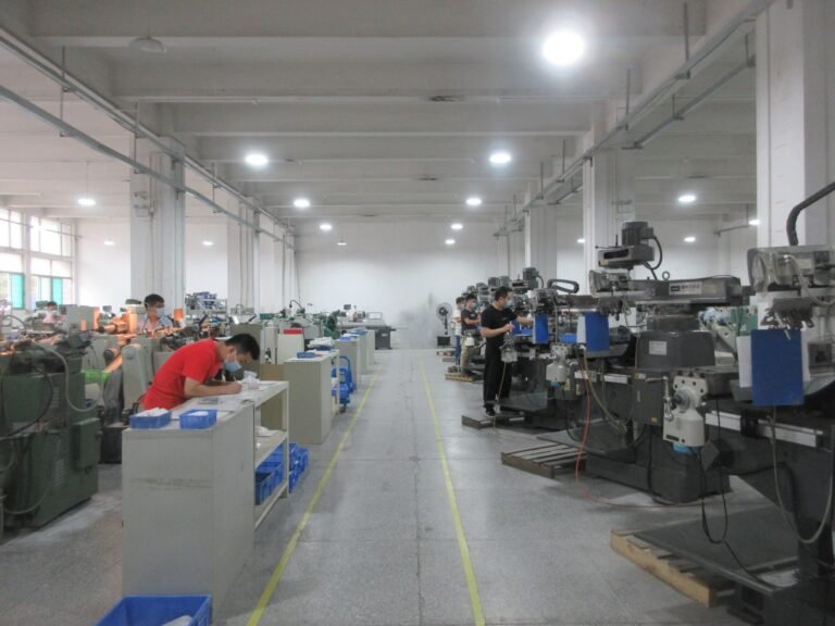
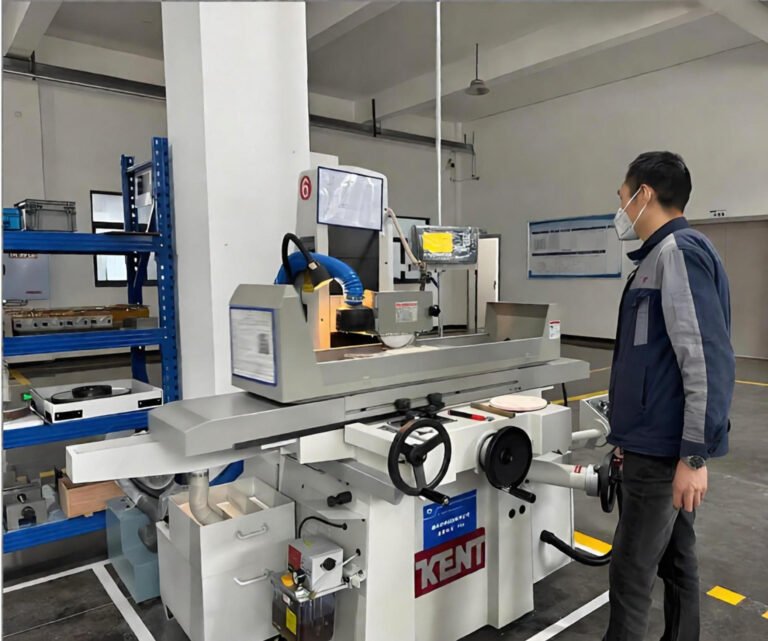
Bore and outside diameter grinding
The bore and the outside diameter are both ground and their concentricity is held from a single setup.
Bore honing to finish
Where the bushing runs against a shaft or a plunger, the bore finish is controlled separately from the bore diameter.
Wall thickness and concentricity
Both are inspected on the finished part because a bushing that is dimensionally correct but eccentric will not run true.
Where the difficulty sits
- Achieving bore roundness in a short, stiff section
- Holding wall thickness concentric around a small bore
- Machining grooves and slots inside a bore
- Controlling bore surface finish for a bearing fit
- Maintaining perpendicularity of the end faces to the bore
LimitBrittle material fails differently from metal. A feature that is merely difficult in steel can be impossible in ceramic, and the review states which of the two applies.
Confirmed capability
Customizable geometry and precision capability
Everything below is produced from the customer drawing. The figures are what the shop is confirmed to hold on the features this family carries, not a general tolerance for the whole part.
| Feature | Confirmed | Applies to |
|---|---|---|
| Hole diameter tolerance | 0.003 mm | Bores, including long small bores |
| Roundness | 0.0005 mm | Bore and outside diameter |
| Parallelism | 0.002 mm | End faces against the bore axis |
| Surface roughness | Ra 0.02 µm | Bore where a shaft runs |
| Minimum slot width | 0.2 mm | Oil grooves and relief slots inside bores |
Capabilities depend on material, geometry, feature size and finishing requirements. Critical dimensions are reviewed against the drawing.
| Measurement requirement | How it is verified |
|---|---|
| Bore diameter and roundness | Bore gauge backed by a roundness check, because two-point measurement cannot see lobing |
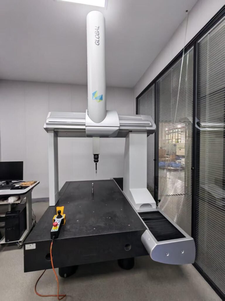
| Concentricity between bore and outside diameter | Rotation on centres or CMM in a single setup |
| Wall thickness and its uniformity | Ball micrometer or ultrasonic spot checks around the circumference and along the length |
| Perpendicularity of the end faces to the bore axis | CMM, or surface plate with square and indicator, seated on the datum face without rocking |
| Surface roughness of the bore where a shaft runs | Stylus profilometer where bore access allows; smaller bores are verified by process control |
Procurement risks
What goes wrong, and where it is avoided
A ceramic bushing on a soft steel shaft can wear the shaft rather than the bushing; the shaft hardness belongs in the enquiry.
A dimensionally correct but eccentric bushing runs out in service; concentricity is inspected as its own feature.
A split bushing carries a chip-prone edge at the split; the edge break requirement should be stated.
A bore finished smoother than the fit requires adds lapping cost; the bearing intent governs the callout.
Applications
Where the family is used
Component examples only. No customer names are published.
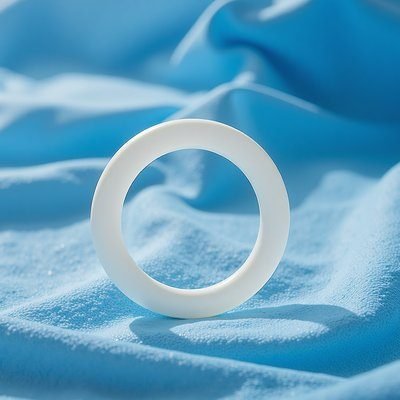
Thermal break bushings between hot and cold assemblies
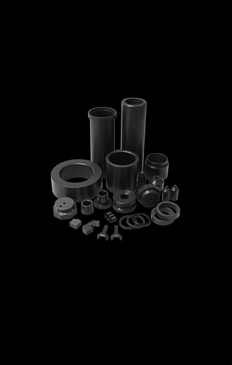
Wear bushings in pumps, valves and mixers
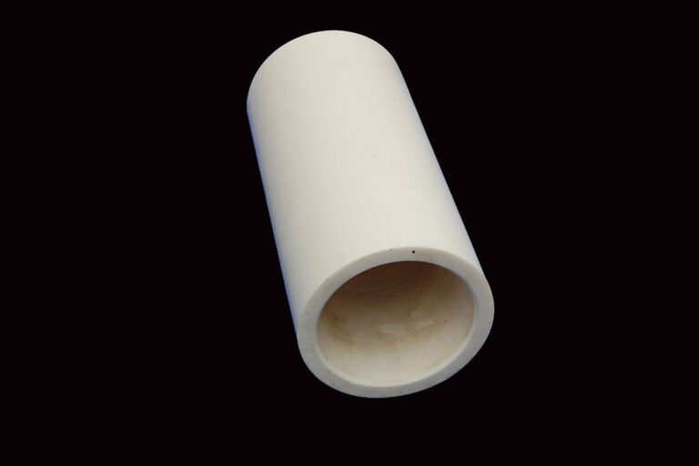
Bearing bushings and sleeve bearings
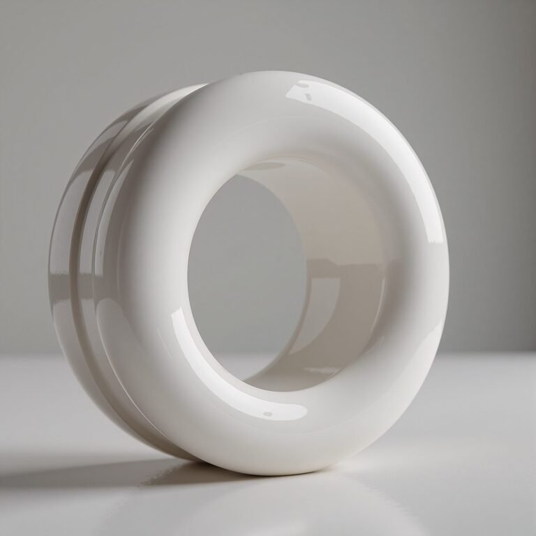
Insulating bushings and feedthrough insulators
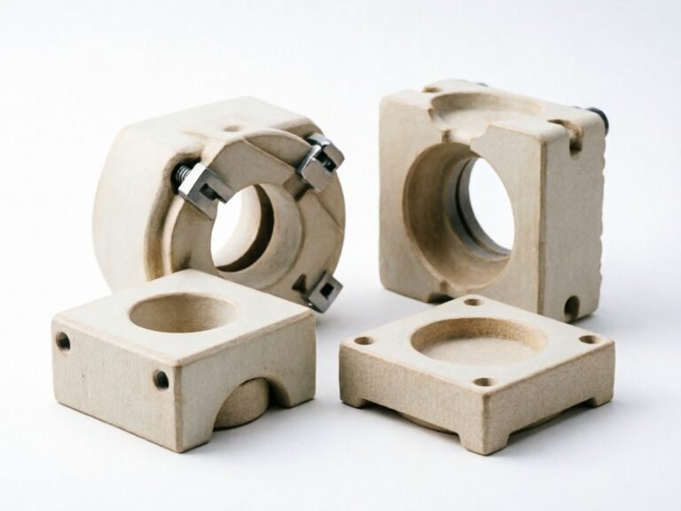
Guide bushings in fixtures, jigs and dies
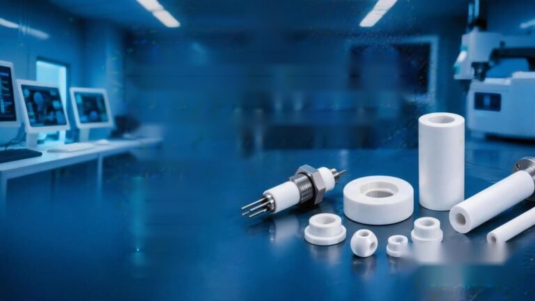
Threaded and flanged bushings
- Wear bushings in production machinery
- Insulating bushings in electrical assemblies
- Pump and valve guide bushings
- Guide bushings in tooling and fixtures
- Corrosion-resistant sleeves in process equipment
Engineering FAQ
Frequently asked
Can a ceramic bushing run directly on a steel shaft?
It can, but the pairing should be reviewed. Ceramic on hardened steel works in many applications, while ceramic on soft steel can wear the shaft rather than the bushing.
Do you produce split bushings?
Yes, by grinding the split after forming. The split introduces an edge that is prone to chipping, so the edge break requirement should be stated on the drawing.
Request a quote
Have a Ceramic Bushing Drawing?
Geometry, material, quantity and the dimensions that matter. You get an engineering review before any price is given. Supplying the items below with the drawing removes the most common cause of a revised quotation.
- Bore and outer diameter tolerances with the fit intent
- Concentricity requirement
- End face perpendicularity
- Groove or slot geometry, including position tolerances
- The shaft material and hardness the bushing runs against
| Type | Form |
|---|---|
| Plain cylindrical bushings | with a through bore |
| Shouldered and flanged bushings | locating and mounting forms |
| Bushings | with oil grooves, slots or relief features |
| Tapered and split bushings | clamping and adjustment forms |
| Thin-wall insulating bushings | feedthrough and isolation duty |