Manufacturing capability
Complex Ceramic Geometry Machining
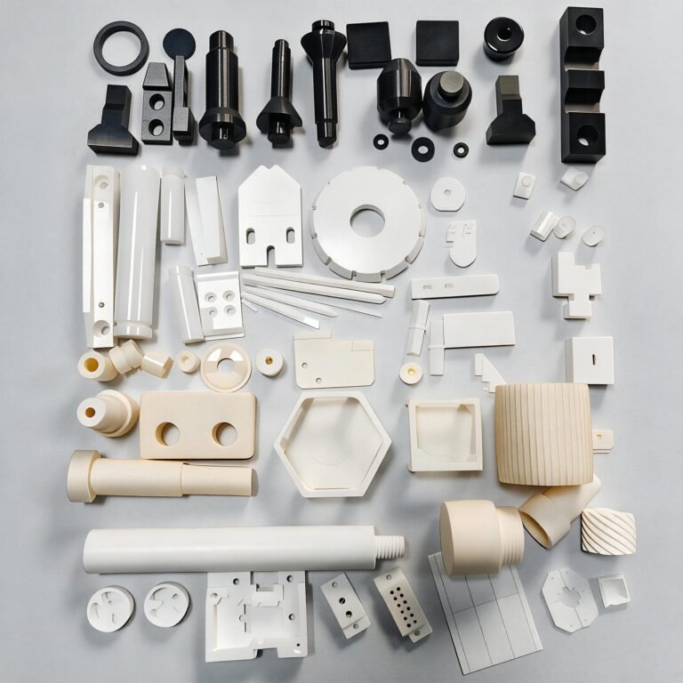
Profiles, pockets, tapers, undercuts and intersecting features in hard, brittle technical ceramics, with the fixturing planned before machining starts.
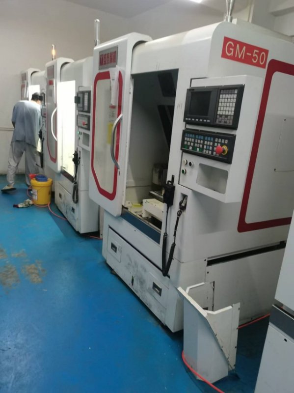
Feasible geometry
What can be produced
Complexity in ceramic is limited by how the material behaves under the tool, not by the number of axes available.
| Feature | Manufacturing route | Primary constraint | Datum risk | Inspection method |
|---|---|---|---|---|
| Profiles and tapers | Can often be produced by form grinding where tool access, radius and feature depth permit | Wheel dressing accuracy and feature depth vs wheel radius | Form is verified against the datum, not a mating surface | Optical or CMM profile comparison |
| Pockets and recesses | Machined with fine tooling where the entry allows | Depth-to-width ratio and tool rigidity | Pocket floor may become a false datum if not called out | CMM or video measurement |
| Intersecting bores | Drilled and ground where entry angles allow tool access | Entry angle and bore alignment | The first bore becomes the reference for the second | CMM for position; bore gauge for diameter |
| Undercuts | Specialised tooling or split fixturing, with an extra setup | Tool access and edge support at the undercut mouth | Extra setup adds datum transfer error | Optical edge inspection plus CMM |
| Thin walls | Produced down to sub-millimetre sections with support during machining | Wall stiffness under clamp and wheel load | Measured in a fixture; free state reads deflection | CMM or video measurement in fixture |
| Sharp internal corners | Not producible; a radius is required | No tool can produce an internal sharp corner | Corner becomes a stress raiser in service | Radius verified optically |
| Deep narrow slots | Ground or machined where the tool can clear | Slot width, not depth alone, sets the limit | Slot position tolerance drives the setup | Video measuring system |
A drawing that combines several of these features is produced as a custom complex ceramic part, which is the family page for geometry that no single shape describes. The shapes that do fall into one category are listed under all component families.
Multi-axis and fixturing
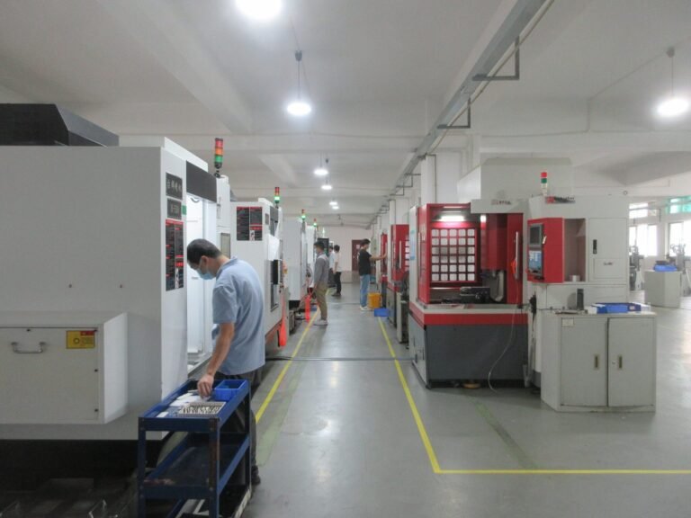
The geometry is only half the problem. Holding a brittle part without inducing stress is the other half.
Rules of thumb for brittle material
These are the constraints that most often force a design change late in a project.
Radii, not corners
Sharp internal corners concentrate stress and cannot be produced. Add the largest radius the function allows.
Support thin sections
A thin wall deflects under clamping and chipping under the tool. Design a supported wall or accept a looser tolerance.
Avoid stress raisers
Holes near edges, abrupt section changes and sharp shoulders are where ceramic parts break in service as well as in production.
Tolerance the function
A complex part with three tight dimensions is cheaper than the same part with thirty.
Process to measurement method
A complex part is measured as a part rather than feature by feature. The datum scheme decides how it is set up, and the setup decides what the numbers mean.
| Requirement | How it is verified |
|---|---|
| Compound datum features | CMM against the datum scheme on the drawing, with the setup stated in the report |
| Free-form and contoured surfaces | CMM point cloud compared with the model at an agreed point density |
| Angular and tapered faces | CMM, with the angle measured against the datum rather than against a mating surface |
| Bores at an angle to the main axis | Optical or video measurement for position, bore gauge for diameter |
| Thin walls and unsupported sections | Measured in a fixture, because an unsupported measurement reads the deflection rather than the part |
| Slot and pocket width | Optical or video measurement, which does not load the edge |
| Edge condition throughout | Optical edge inspection against the criterion agreed at review |
Confirmed capability figures
Figures below are the capability the shop is measured on. They are feature-specific, not a general tolerance.
Capabilities depend on material, geometry, feature size and finishing requirements. Critical dimensions are reviewed against the drawing.
The part and the process
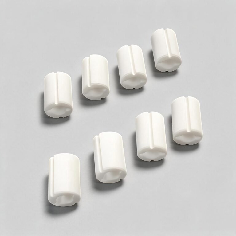
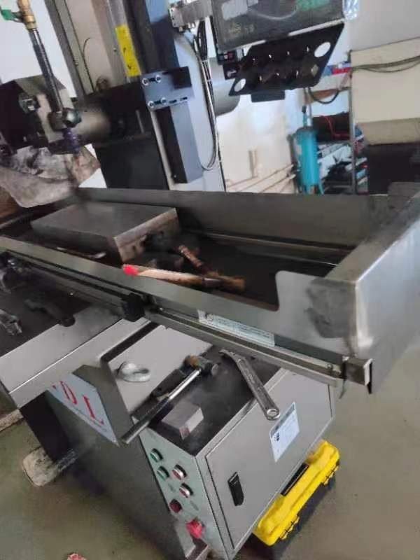
Frequently asked
Is five-axis machining necessary for my part?
Only when features sit at compound angles or must be reached without re-datuming. Many complex parts are produced more accurately with a well-planned sequence on fewer axes.
How thin can a wall be?
Sub-millimetre sections are produced, but the wall thickness that can also hold a tight tolerance depends on the material, the wall height and whether it can be supported during machining.
Can you produce an undercut?
Yes, with specialised tooling or by splitting the fixture and re-datuming. It adds a setup and should be flagged early because it affects both cost and achievable position tolerance.
What if my design cannot be made at all?
You receive a written explanation with the specific constraint and a feasible alternative, before the quotation is issued. Designs are not changed without your agreement.
Send us the drawing and the requirement
We review manufacturability, tolerance and inspection method before quoting.