
Component family
Ceramic Plates and Blocks
Plates, blocks, discs and carriers in ceramic, specified mainly for flatness, thermal behaviour and resistance to wear or chemical attack.
- Ground faces and edges
- Flatness and parallelism
- Pockets, bores and slots
- Thickness held to the drawing
A ceramic plate or block is a prismatic component machined from sintered technical ceramic with ground faces. The family covers base plates, setter plates, carriers, discs and wear plates. Ceramic is chosen where the plate must stay flat and stable at temperature, resist wear or chemical attack, or insulate electrically. The engineering core of the part is the relationship between flatness, parallelism and thickness – and the figures the shop confirms for these are feature and size bound, so a tighter figure held on a small plate is not automatically available on a large one.
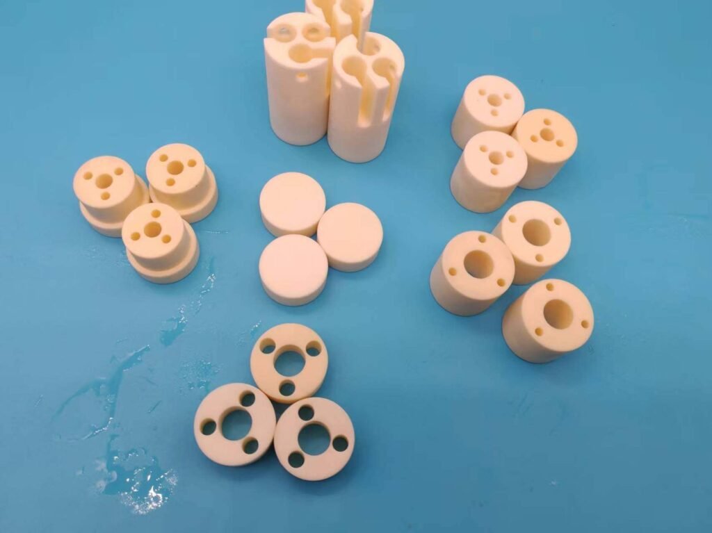
Machined ceramic plates, discs and blocks in alumina, silicon carbide, aluminum nitride and boron nitride — faces, edges and features finished to the drawing.
Critical features
What this geometry is judged on
Each row ties one feature to why it matters, where it is at risk in manufacture, and how it is verified. The confirmed figures for these features sit further down the page, tied to the feature they were measured on.
Ground faces
Both main faces are ground. Flatness is called on a defined area rather than across the whole surface.
Thickness
Ground between the faces, so thickness and parallelism are one operation rather than two.
Pockets and recesses
Cut before or after firing depending on depth and the tolerance on the floor.
Bores and locating features
Positioned from the datum edges on the drawing, which is why the datum scheme is settled at review.
Edge profiles
Chamfers and edge radii are agreed, because an unspecified edge is the most common source of disagreement on a plate.
Circular discs and flanges
Turned and ground where the part is round rather than rectangular.
| Feature | Why it matters | Manufacturing risk | Inspection method |
|---|---|---|---|
| Face flatness | The plate seats and carries on it | Holding flatness over a large area in a brittle material | CMM scan or surface plate sweep over the stated area |
| Face parallelism | Thickness is held between the faces | Keeping faces parallel across the full plate | CMM with both faces in one setup |
| Thickness | Sets the spacing in the assembly | Managing thin plates that deflect under grinding load | Micrometer over a defined grid |
| Feature position | Bores and pockets locate the assembly | Maintaining flatness after features are cut | CMM position check to the datum edges |
| Functional-face finish | Sliding or sealing happens on it | Grinding without stressing the thin section | Stylus profilometer on the called-out zone |
Possible ceramic materials
Material options and the reason behind each
The material is chosen from the dominant requirement. Where two requirements conflict, the trade-off is explained before quoting.
Where the plate must conduct heat and remain electrically insulating
Release and non-wetting surfaces
Process routes
How these parts are actually made
The route is chosen from the geometry and the tolerance, not from the material alone. It is stated with the quotation so the price can be read against the method.
Surface grinding and lapping
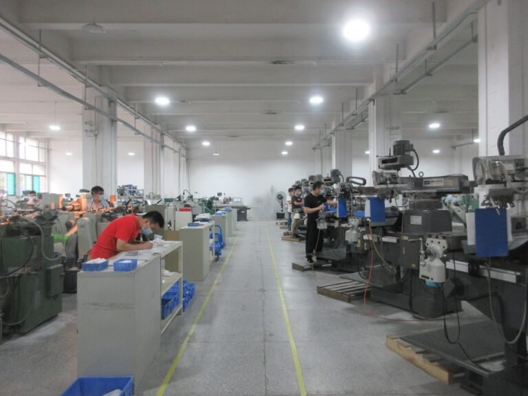
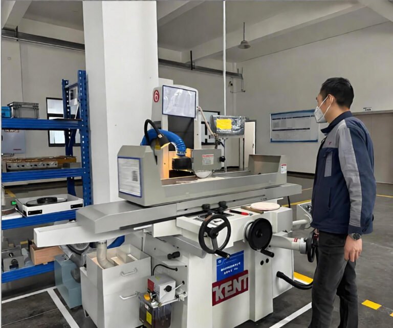
Flatness, parallelism and thickness are produced by surface grinding, and lapping follows when a finer finish or tighter flatness is required.
Hole and slot machining
Diamond core drilling and slot grinding produce the hole patterns, with the minimum slot width governing how narrow the features can be made.
Flatness inspection
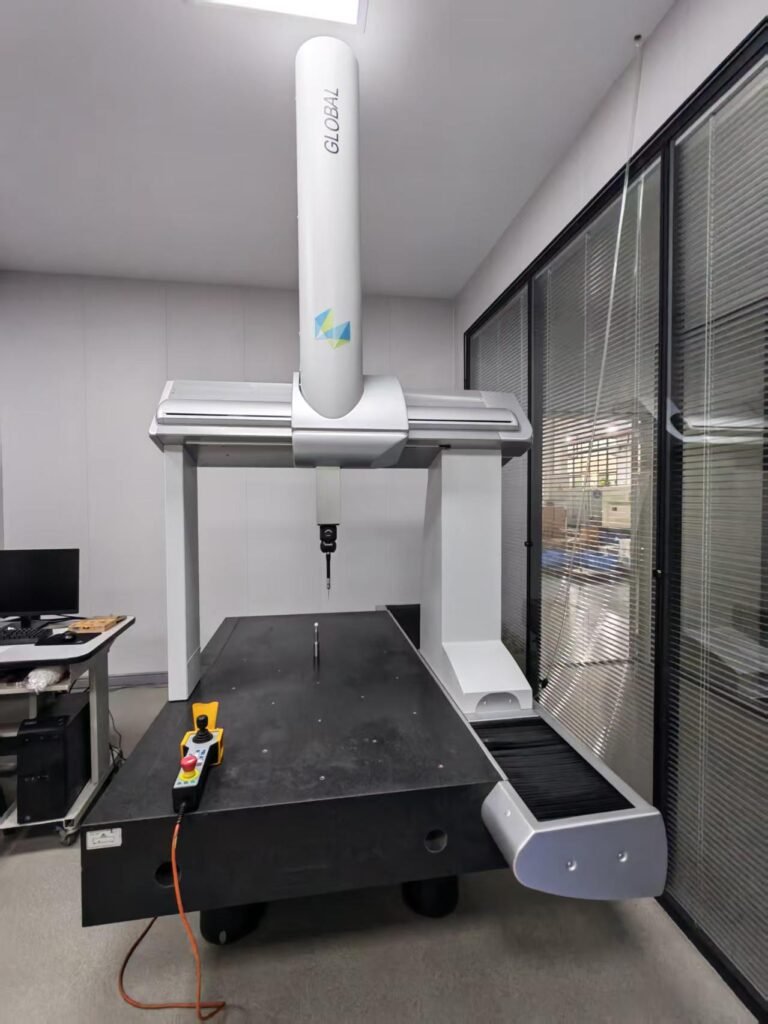
Flatness and parallelism are measured across the whole face rather than at a single point, because a plate is judged over its full area.
Where the difficulty sits
- Holding flatness over a large area in a brittle material
- Keeping the two faces parallel across the full plate
- Machining pockets without inducing cracks at the corners
- Managing thin plates that deflect under grinding load
- Maintaining flatness after bores or pockets are cut
LimitBrittle material fails differently from metal. A feature that is merely difficult in steel can be impossible in ceramic, and the review states which of the two applies.
Confirmed capability
Customizable geometry and precision capability
Everything below is produced from the customer drawing. The figures are what the shop is confirmed to hold on the features this family carries, not a general tolerance for the whole part.
| Feature | Confirmed | Applies to |
|---|---|---|
| Parallelism | 0.002 mm | Opposed faces of a plate or a block |
| Minimum slot width | 0.2 mm | Slots, pockets and narrow cut features |
| Hole diameter tolerance | 0.003 mm | Bores and locating holes |
| Surface roughness | Ra 0.02 µm | Functional faces |
Capabilities depend on material, geometry, feature size and finishing requirements. Critical dimensions are reviewed against the drawing.
| Measurement requirement | How it is verified |
|---|---|
| Flatness over the full face or the defined area | CMM scan, or surface plate with indicator sweep; a thin plate is supported on a defined datum plane so deflection is not read as flatness error |
| Parallelism between the two main faces | CMM with both faces measured in one setup |
| Thickness tolerance | Micrometer over a defined grid; grid density sets the confidence |
| Position of bores and pockets relative to the datum edges | CMM from the datum edges the drawing identifies |
| Surface finish where the plate is functional | Stylus profilometer traced on the zone the callout marks |
Procurement risks
What goes wrong, and where it is avoided
The confirmed parallelism figure is feature-bound; it is not automatically available on a large or thin plate, where flatness is size and thickness limited.
Unspecified edges are the most common source of acceptance disputes on a plate; edge breaks should be called out.
A pocket cut too deep relative to the remaining section cracks in service; the depth limit is reviewed at quotation.
A plate measured flat on a surface plate but mounted on an uneven seat deflects in service; the mounting plane matters.
Applications
Where the family is used
Component examples only. No customer names are published.
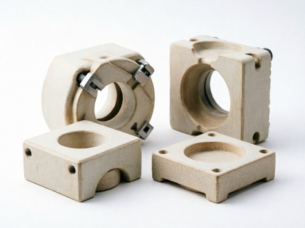
Blocks with pockets, bores and locating features
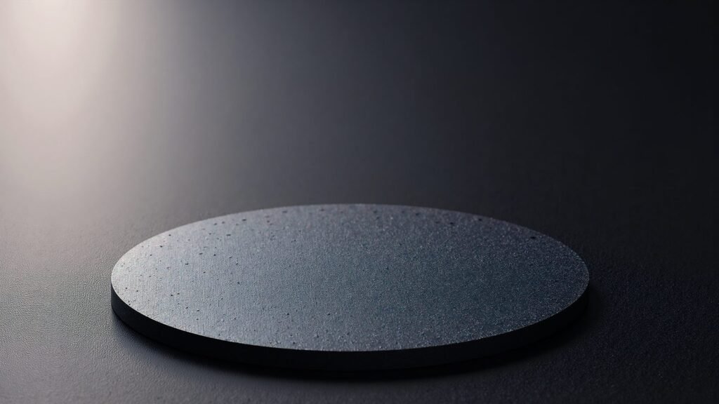
Circular discs and flanges

Wear plates with an edge or surface profile
- Base plates and machine beds
- Furnace setters and kiln furniture
- Semiconductor and coating carriers
- Wear plates in material handling
- Insulating separators in electrical equipment
Engineering FAQ
Frequently asked
How flat can a large plate be made?
Flatness is limited by plate size and thickness rather than by the grinding process alone. A thin plate over a large area presents the greatest difficulty, and the achievable value is confirmed from the drawing.
Can you machine pockets into a fired plate?
Yes, by diamond grinding. Corner radii are required, and the pocket depth relative to the remaining section is reviewed so the plate does not become too thin locally.
Request a quote
Have a Ceramic Plate or Block Drawing?
Geometry, material, quantity and the dimensions that matter. You get an engineering review before any price is given. Supplying the items below with the drawing removes the most common cause of a revised quotation.
- Flatness and parallelism with the datum face identified
- Thickness and its tolerance
- Position and size tolerances of bores and pockets
- Whether edge breaks are required on all faces
- The plate size and thickness, because the achievable flatness follows from them
| Type | Form |
|---|---|
| Rectangular and square plates | with ground faces |
| Circular discs and flanges | ground and profiled |
| Blocks | with pockets, bores and locating features |
| Setter and carrier plates | with recesses |
| Wear plates | with an edge or surface profile |