Engineering guide
Precision Ceramic Inspection Methods
How ceramic parts are dimensionally verified, why contact probing is avoided on some features, and how to set an inspection plan that both sides can reproduce.
Instruments
What is used and for what
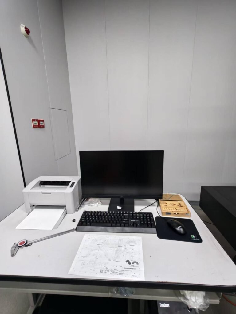
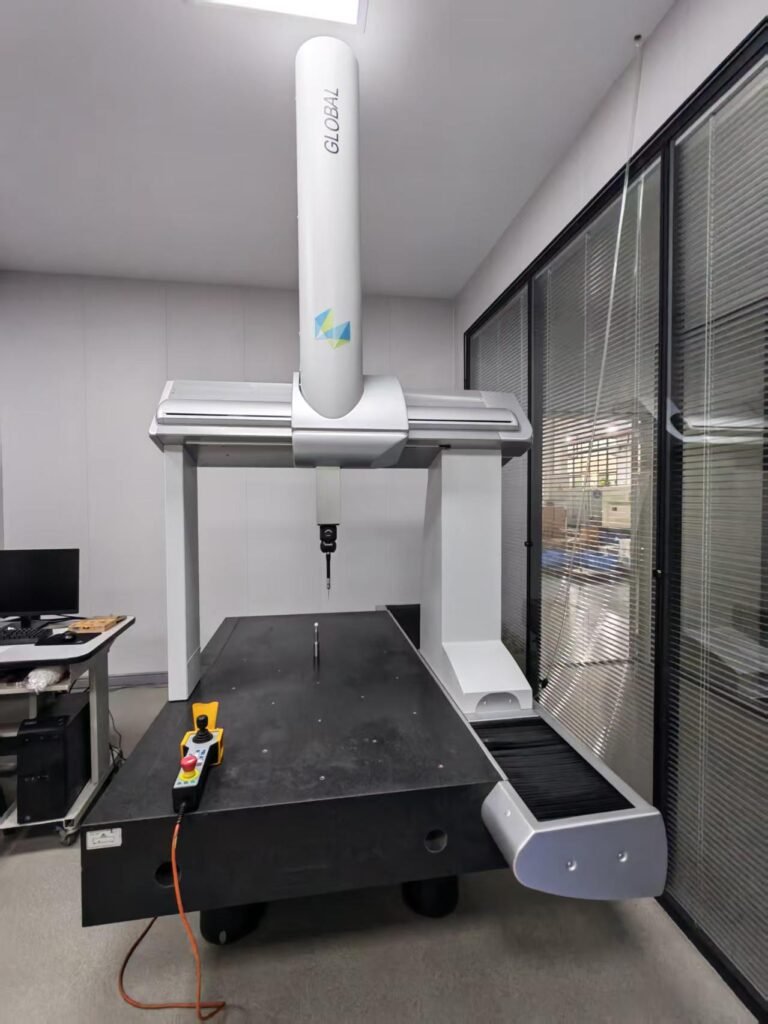
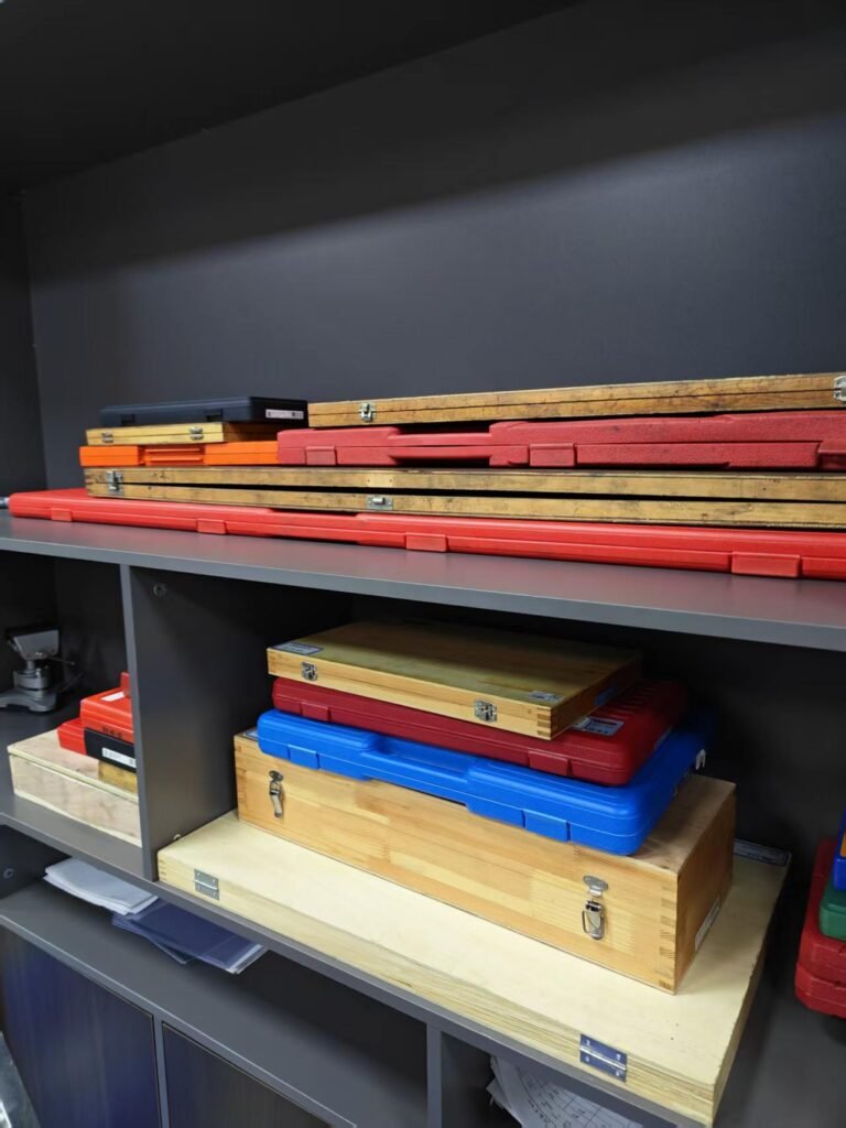
An inspection room for precision ceramic parts needs seven instrument types, each tied to the feature it verifies: a coordinate measuring machine for position, form and complex geometry; video and optical measurement for small features and edges; a height measuring instrument for steps and reference dimensions; a surface roughness tester for Ra and surface texture; micrometers and bore gauges for in-process checks; a roundness instrument for cylindrical form; and a surface plate with gauge blocks as the flatness reference. Capability is shown through the inspection plan rather than through a list of machines: critical and functional dimensions checked on every part, general dimensions sampled at an agreed frequency, and the first article of a new design or revision fully verified. The method is agreed before machining, because measuring the same way on both sides settles a disagreement before the parts ship rather than after.
| Instrument | Used for |
|---|---|
| Coordinate measuring machine | Position, form and complex geometry |
| Video and optical measurement | Small features, edges and non-contact verification |
| Height measuring instrument | Height, step and reference dimensions |
| Surface roughness tester | Ra and surface texture |
| Micrometers and bore gauges | In-process dimensional checks |
| Roundness instrument | Roundness and cylindrical form |
| Surface plate and gauge blocks | Flatness reference and traceability |
How those tolerances are written on the drawing in the first place is set out in GD and T for ceramic parts. What is issued with a shipment, and how it is controlled, is described under quality and documentation. An application where the inspection criterion is set by the process rather than by the drawing alone, because an edge inside a chamber is a particle source, is set out under edge criteria for chamber components.
Why the method has to be agreed
Two methods measuring the same feature can report different values and both be correct.
- Datum scheme, which determines the reference for every value
- Measurement temperature, which matters at tight tolerances
- Contact against non-contact, which changes the measured value on edges and flexible features
- Number and position of measurement points on a form tolerance
- Filter and evaluation settings on a roughness measurement
What to check on every part and what to sample
| Category | Treatment |
|---|---|
| Critical and functional dimensions | Checked on every part |
| General dimensions | Sampled at an agreed frequency |
| First article of a new design | Fully verified |
| Surface finish | Checked on the surfaces that carry a callout |
| Visual and edge | Every part |
When values disagree
Almost all disagreements come from method, not from the part.
Where the work is done
Frequently asked
Do you supply a dimensional report?
Yes, when it is requested on the purchase order. It lists the dimensions in the agreed inspection plan with the measured values.
Can I specify my incoming inspection method?
Yes, and it helps. Measuring the same way on both sides settles any disagreement before the parts ship rather than after.
Why is contact probing avoided on some features?
It can damage a thin edge or a micro feature. Optical and video measurement is used where contact would alter the measurement or the part.
How often should a part be checked in production?
Critical dimensions on every part, general dimensions sampled, first article fully verified. The exact plan is agreed per order.
Have a drawing that this guide applies to?
Send it with the material and the quantities. The review confirms what is achievable before any price is issued.