
Component family
Ceramic Shafts and Pins
Shafts, plungers, pins and stems in ceramic, where the driver is wear resistance, electrical isolation or dimensional stability over temperature.
- Steps, shoulders and grooves
- Ground functional diameters
- Threaded pin variants
- Finish on sliding diameters
A ceramic shaft, pin, plunger or stem is a cylindrical component machined from sintered technical ceramic and finished by grinding. Five part types sit in this family, and each is toleranced differently: a locating pin carries position, a wear pin carries abrasion, a shaft carries bending load, a plunger carries a lapped sealing diameter, and a valve stem carries alignment with its seat. Ceramic is chosen where the duty needs wear resistance, electrical isolation or dimensional stability over temperature that a steel part cannot hold.
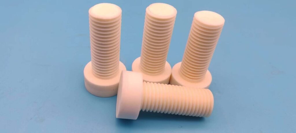
Machined ceramic shafts, pins and plungers in zirconia, silicon nitride, alumina and silicon carbide — diameters, shoulders and finishes held to the drawing.
Critical features
What this geometry is judged on
Each row ties one feature to why it matters, where it is at risk in manufacture, and how it is verified. The confirmed figures for these features sit further down the page, tied to the feature they were measured on.
Functional diameter
Ground to the drawing, and the diameter the fit is judged on.
Steps and shoulders
Shoulder faces are ground square to the axis rather than left as-fired.
Retaining and relief grooves
Ground after firing, so the groove floor holds its position along the axis.
Plunger sealing diameters
Lapped where the plunger runs in a sealed bore.
Threads
Ground, not rolled. A thread in ceramic is a grinding operation, so the profile is agreed before quoting.
Tapers and needle profiles
Ground as a form, so the angle is held over the length rather than at one point.
| Feature | Why it matters | Manufacturing risk | Inspection method |
|---|---|---|---|
| Functional diameter | The fit or the seal is judged on it | Grinding a slender shaft without deflection or taper | Micrometer with CMM roundness backup |
| Straightness over the working length | The shaft runs true in the assembly | Deflection during grinding on long slender parts | Between-centres indicator or CMM axis scan |
| Stepped-diameter concentricity | Working sections stay aligned with each other | Holding concentricity across separate setups | CMM in a single setup |
| Shoulder perpendicularity | Seats against the shoulder without tilt | Chipping on shoulder transitions | CMM squareness check from the shaft axis |
| Sealing-diameter finish | Seals against the counterface bore | Producing a lapped diameter that seals without a soft counterface | Stylus profilometer on the functional band |
Possible ceramic materials
Material options and the reason behind each
The material is chosen from the dominant requirement. Where two requirements conflict, the trade-off is explained before quoting.
High strength and wear resistance; suited to plungers and pins under load
Zirconia page →Where insulation or corrosion resistance is the main requirement and load is moderate
Alumina page →Process routes
How these parts are actually made
The route is chosen from the geometry and the tolerance, not from the material alone. It is stated with the quotation so the price can be read against the method.
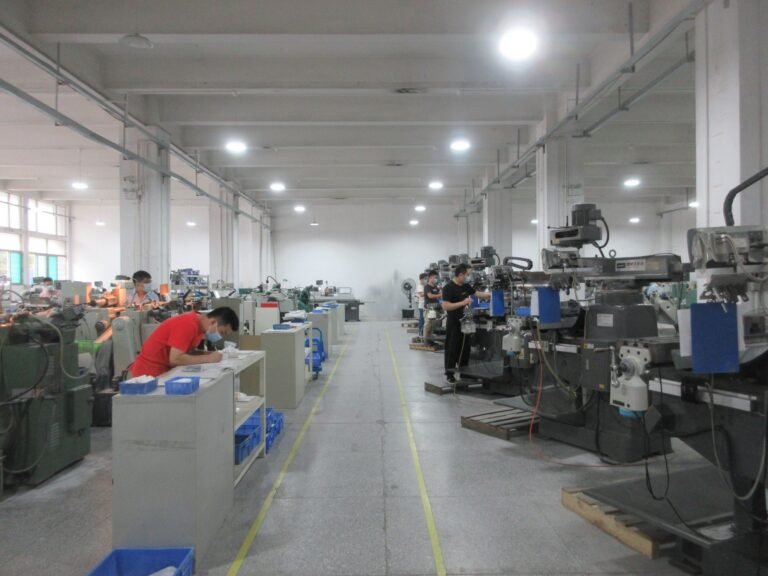
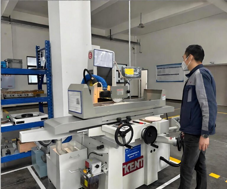
Cylindrical grinding
Diameter, straightness and roundness are produced by grinding between centres or in a collet, which is what holds a shaft on centre along its length.
Lapping for surface finish
Where the shaft runs in a seal or a bushing, finish is controlled separately from diameter because the two drive different behaviour.
Concentricity control
Steps, shoulders and journals are ground from a single datum so concentricity is held along the whole part.
Where the difficulty sits
- Grinding a long slender shaft without deflection or taper
- Controlling straightness over the full length
- Producing a lapped diameter that seals without a soft counterface
- Holding concentricity between stepped diameters
- Preventing chipping on shoulder transitions
LimitBrittle material fails differently from metal. A feature that is merely difficult in steel can be impossible in ceramic, and the review states which of the two applies.
Confirmed capability
Customizable geometry and precision capability
Everything below is produced from the customer drawing. The figures are what the shop is confirmed to hold on the features this family carries, not a general tolerance for the whole part.
| Feature | Confirmed | Applies to |
|---|---|---|
| Roundness | 0.0005 mm | Ground cylindrical sections and journals |
| Parallelism | 0.002 mm | Shoulder faces against the shaft axis |
| Surface roughness | Ra 0.02 µm | Lapped plunger sealing diameters |
| Hole diameter tolerance | 0.003 mm | Cross holes and axial bores |
| Minimum slot width | 0.2 mm | Flats, keyways and narrow slots |
Capabilities depend on material, geometry, feature size and finishing requirements. Critical dimensions are reviewed against the drawing.
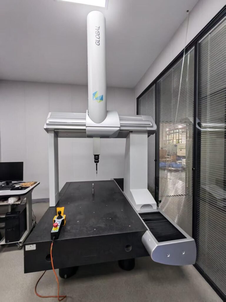
| Measurement requirement | How it is verified |
|---|---|
| Diameter tolerance on the functional section | Micrometer, backed by CMM roundness because two-point gauges can miss lobing |
| Straightness and cylindricity over the working length | Rotation between centres with an indicator, or a CMM axis scan |
| Concentricity between stepped diameters | CMM in a single setup so the reference does not move between features |
| Shoulder perpendicularity to the axis | CMM squareness check from the shaft axis |
| Surface finish on the sliding or sealing diameter | Stylus profilometer traced on the functional band, not the whole diameter |
Procurement risks
What goes wrong, and where it is avoided
A slender shaft toleranced for straightness beyond what grinding holds at the stated length-to-diameter ratio forces a design change; the ratio is reviewed before quoting.
Threaded ceramic ends are brittle in bending; a thread should not carry structural load and the drawing should say so.
A plunger lapped without the counterface bore specified can leak even when both parts are in tolerance; the mated bore belongs in the enquiry.
Shoulder-transition chips are a mounting risk; edge breaks should be specified rather than left to default.
Applications
Where the family is used
Component examples only. No customer names are published.
- Metering and dosing pumps
- Valve stems and needle valves
- Wear-resistant guide and locating pins
- Electrical isolation in actuators
- Analytical and dosing equipment
- Ceramic shaft rods and plungers for pumps and dispensers
- Spindle and centrifuge shafts
- Locating pins, dowel pins and fixture pins
- Valve stems and needle shafts
- Pump plungers and ceramic pistons
- Shaft and pin components for analytical instrumentation
Engineering FAQ
Frequently asked
Can you cut threads in ceramic?
Yes, by grinding. A ground thread is produced to the drawing specification, but a ceramic thread is brittle and should not be used as a high-cycle fastening joint.
How long a shaft can you grind?
Length is limited by deflection during grinding rather than by machine travel. The length-to-diameter ratio is what matters, and it is reviewed from the drawing.
Request a quote
Have a Ceramic Shaft or Pin Drawing?
Geometry, material, quantity and the dimensions that matter. You get an engineering review before any price is given. Supplying the items below with the drawing removes the most common cause of a revised quotation.
- Overall length with the datum end identified
- Diameter tolerances by section, not as a general note
- Straightness or runout requirement over the working length
- Thread specification if a threaded variant is needed
- Which of the five part types the drawing is: locating pin, wear pin, shaft, plunger or valve stem
| Type | Form |
|---|---|
| Straight shafts | with steps, shoulders and retaining grooves |
| Plungers | with lapped sealing diameters |
| Locating and dowel pins, including threaded variants | ground and centred |
| Valve stems and needle profiles | profiled to the drawing |
| Tapered and shouldered pins | centre-driven forms |