Manufacturing capability
Ceramic Inspection and Metrology
What is measured, on which instrument, and what documentation is issued with a shipment of custom ceramic components.
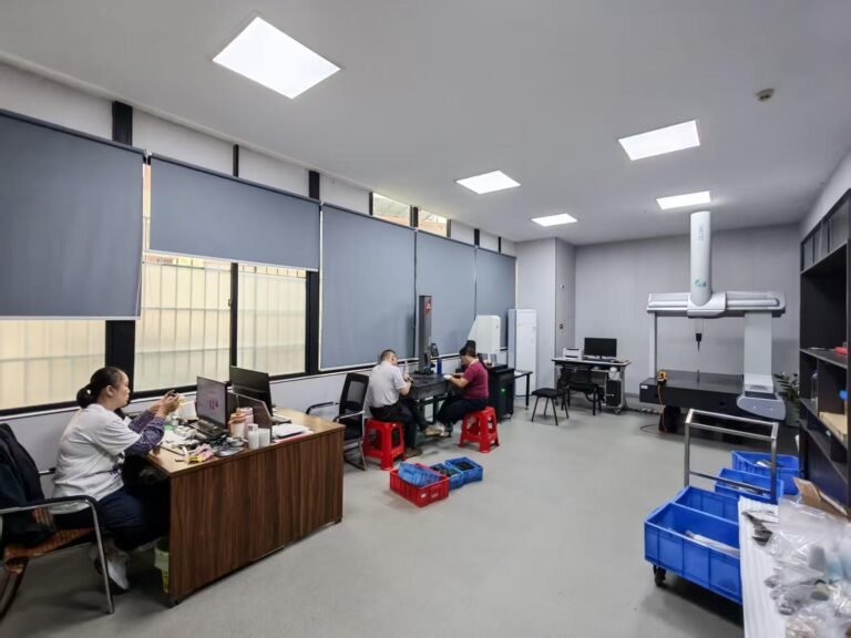
Equipment
What the parts are measured on
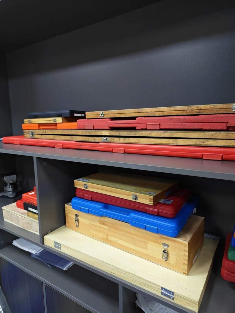
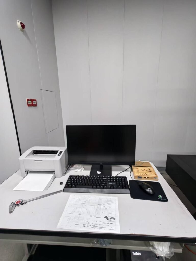
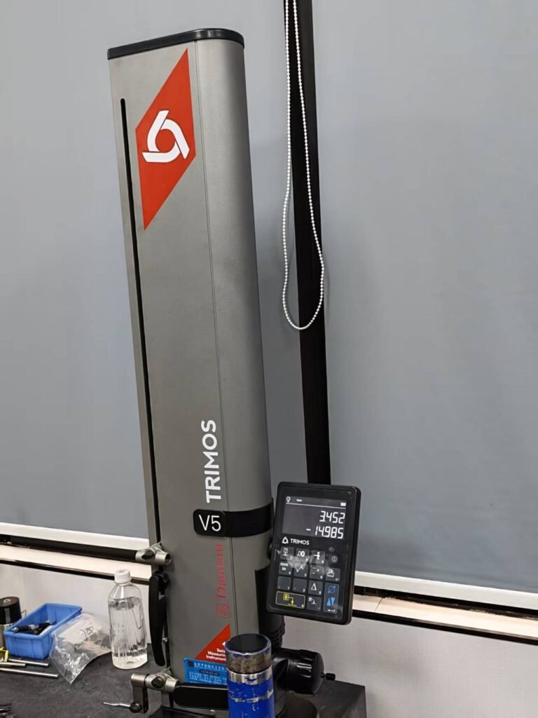
Contact and non-contact instruments are used depending on the feature. The choice is made during the engineering review, not after machining.
| Instrument | Used for |
|---|---|
| Coordinate measuring machine | Position, form and complex geometry in three dimensions |
| Video and optical measuring system | Small features, edges and non-contact verification |
| Height measuring instrument | Height, step and reference dimensions |
| Surface roughness tester | Ra and surface texture on sealing and sliding faces |
| Micrometers and bore gauges | Fast in-process dimensional checks |
| Roundness instrument | Roundness and cylindrical form on bores and shafts |
| Gauge blocks and calibration set | Traceability of the measurement chain |
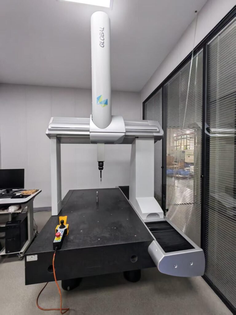
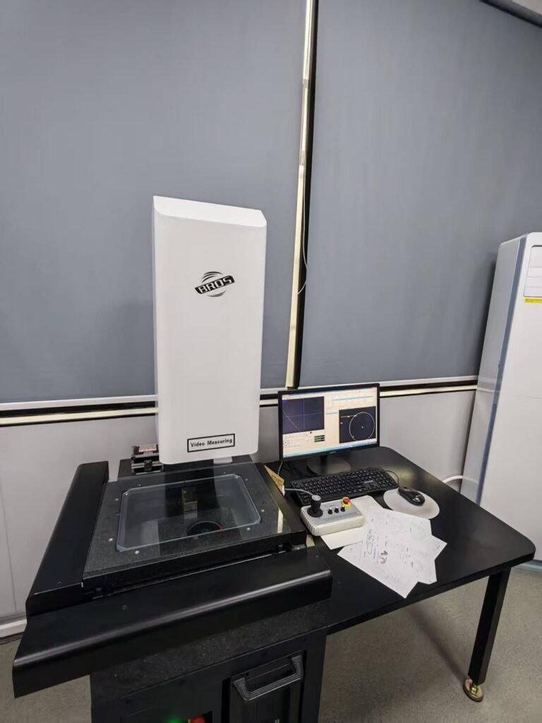
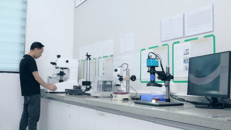
Which dimension is checked how
Ceramic cannot be reworked or straightened, so the measurement method is part of the process design.
| Requirement | Method |
|---|---|
| Hole diameter tolerance | Bore gauge for in-process, CMM or optical for the report |
| Roundness | Roundness instrument |
| Parallelism and flatness | CMM with the datum scheme from the drawing; the height instrument covers simpler step features |
| Position | CMM against the datum scheme, or the video system for 2D position on small features |
| Concentricity | CMM with the datum features established in the drawing’s order |
| Minimum slot width | Optical or video measurement |
| Surface roughness | Surface roughness tester on the specified surfaces |
| Edge condition | Visual and optical inspection against the agreed edge criterion |
What can ship with the order
The document set is agreed on the purchase order, so it is planned into inspection rather than assembled retrospectively.
Dimensional report
Measured values for the dimensions listed in the agreed inspection plan.
First article inspection
Full dimensional and visual verification of the first part of a new design or revision.
Material certificate
Certificate of conformity and material test report for the grade used.
The document set matters most where the drawing is checked again after delivery, by someone who was not in the build. Programmes with an audited supply chain, such as ceramic parts for aerospace, fix the report format before the first part is machined rather than afterwards. Where the accepted value is a relationship between features rather than a size, which is the usual case in precision alignment of mating ceramic faces, the datum scheme on the drawing decides what the report is able to prove.
How much is checked
Full dimensional verification of every part is neither necessary nor practical for most projects. The plan separates what must be checked on every part from what is sampled.
- Dimensions the agreed plan assigns to 100 percent inspection, verified on every part
- General dimensions sampled at an agreed frequency
- First article fully verified before the batch continues
- Surface finish verified on the surfaces that carry an Ra callout
- Visual and edge inspection on every part
What makes a part difficult to measure
A part that cannot be measured cannot be accepted, so these findings are as much a design problem as a tolerance problem. They are raised at review, before the inspection plan is agreed.
| Finding | Why it costs | What helps on the drawing |
|---|---|---|
| No datum scheme on a symmetrical part | Orientation is decided at measurement, so no two reports are directly comparable | Add a datum feature, or state in writing that best-fit orientation is accepted |
| Tolerance tighter than the measurement uncertainty | The instrument cannot resolve the difference between an acceptable part and a rejected one | State the functional requirement and let the method decide the number |
| A toleranced feature inside closed geometry | The probe cannot reach it, so the value has to be inferred rather than measured | Open the geometry, or accept an indicated value with the method stated |
| Surface finish specified overall | Every surface is measured, most of them for no functional reason | Restrict Ra to the surfaces that carry the function |
| Edge condition left open | A chip is judged by opinion, and two inspectors can reach different conclusions | Reference a chip criterion or an edge standard |
| A dimension taken from a face used as the machining datum | The datum moves when the face is refinished, so the number shifts with the process | Separate the functional datum from the machining datum where they differ |
The confirmed figures on one scale
The four length figures the inspection room works to, plotted together. They span more than two decades, which is the part a list of numbers does not convey.
- 1Hole diameter0.003 mm
- 2Parallelism0.002 mm
- 3Roundness0.0005 mm
- 4Minimum slot width0.2 mm
Each figure is the value confirmed on this site and none of them carries a tolerance band, because they are capability statements rather than specification limits. Surface roughness is quoted separately: it is measured in micrometres, so it does not belong on this axis.
Where the work is done
Frequently asked
Can I specify the measurement method?
Yes, and it helps. If your incoming inspection uses a particular method, stating it lets us measure the same way and settle any disagreement before the parts ship.
Is full inspection of every part possible?
For critical dimensions yes, at additional cost. For most orders a plan combining full critical measurement with sampled general measurement is both sufficient and more economical.
Do you provide material test reports?
Yes, on request. Material certificates and test reports can be issued with the order, and they are most useful when stated on the purchase order so they are planned in.
How are small or fragile features measured?
Non-contact methods are used. Contact probing can damage a thin edge or a micro feature, so optical and video measurement is applied instead.
What if the measured values differ from my incoming inspection?
Send the report and the method. Measurement differences commonly arise from datum interpretation, instrument method, fixturing, environmental conditions or measurement uncertainty; the methods should be compared before any disposition is made on the parts.
Send us the drawing and the requirement
We review manufacturability, tolerance and inspection method before quoting.