Industry
Power Electronics: Custom Ceramic Components
Insulating and thermally conductive components for power modules, conversion equipment and high-voltage switching assemblies.
Direct answer
What ceramic components does this industry use?
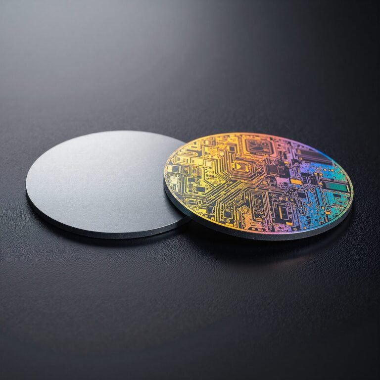
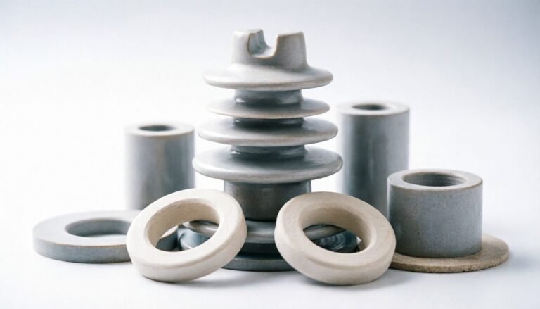
Power electronics uses ceramic parts that carry electrical isolation while heat leaves the module: substrates and insulating bases, bushings and standoffs, insulating barriers, and thermal spacers that combine isolation with heat removal. Aluminum nitride is used where heat has to pass through the insulator; alumina is the economical standard for insulating bodies; silicon nitride carries mechanical and thermal cycling; boron nitride serves machinable specialised paths. Insulating wall thickness, creepage geometry and flatness are functional tolerances, and they are judged from the drawing.
Where the parts sit, and what each one does
Each row ties an equipment class to the ceramic component used in it, the function the part performs, the candidate material, the feature that carries the risk and how that feature is verified. Materials named here are the ones described under material selection below.
| Equipment | Ceramic component | Function | Candidate material | Critical feature | Inspection |
|---|---|---|---|---|---|
| Power modules and converters | Substrates, insulating bases, thermal interfaces | Heat crosses the isolation instead of going around it | Aluminum nitride (AlN); alumina (Al2O3) where the heat flux is lower and cost matters more | Flatness of substrate faces; insulating wall thickness | Flatness on substrate faces; dimensional verification of wall thickness |
| High-voltage switchgear | Insulating bushings, barriers, structural insulators | Isolation held at voltage over long service | Alumina (Al2O3) as the economical standard | Creepage and clearance geometry | Dimensional verification of creepage features; visual inspection for surface contamination |
| Power conversion and inverters | Insulating spacers, mounting plates | Stable geometry under thermal cycling | Silicon nitride (Si3N4); alumina (Al2O3) | Position of mounting holes; flatness | CMM for position; flatness on substrate faces |
| Traction and drive electronics | Thermal and insulating structural parts | Isolation with heat removal under vibration and cycling | Aluminum nitride (AlN); silicon nitride (Si3N4) | Insulating wall thickness around the conducting path | Dimensional verification of wall thickness |
| RF power amplifiers | Substrates and insulated thermal paths | A controlled thermal path with isolation | Aluminum nitride (AlN) | Surface finish where metallisation or bonding follows | Surface roughness where metallisation or bonding follows |
What these parts are judged on
Each row ties one feature to why it matters in service, where it is at risk during manufacture, and how it is measured. The inspection plan is agreed before machining, because a ground ceramic dimension cannot be corrected afterwards.
| Feature | Why it matters | Manufacturing risk | Inspection method |
|---|---|---|---|
| Insulating wall thickness | It carries the isolation around the conducting path | Bore and wall geometry have to be controlled together | Dimensional verification of wall thickness |
| Creepage and clearance geometry | The path along the surface decides the isolation at voltage, not the bulk material on its own | Ribs and grooves require radii, which must be reflected on the drawing | Concentricity and geometry verification; visual inspection |
| Flatness of substrate and mounting faces | A substrate that is not flat does not transfer heat across its full area | Thin insulating sections are limited by handling and chipping | Flatness on substrate faces |
| Surface condition after grinding | Contamination reduces insulation performance and can track under voltage | Cleanliness after grinding; finish specified for coating processes | Visual inspection for cracks and contamination; surface roughness where bonding follows |
| Concentricity of the conducting path | The isolation distance depends on it | Datum transfer between setups loses concentricity | Concentricity verification of the conducting path and outer geometry |
What the process demands of the material
The conditions below act on the part in service. Each one narrows the material or the geometry, and stating them is what turns the material choice into an engineering decision rather than a preference.
Voltage
The part carries the isolation, so dielectric strength and volume resistivity decide the grade.
Thermal load
Heat has to leave the module, which is what brings aluminum nitride into the conversation.
Power cycling
Cycling stresses the substrate and the bond line, so expansion mismatch matters as much as raw strength.
Creepage and clearance
Geometry and surface condition decide the path along the surface, not the bulk material on its own.
Flatness
A substrate that is not flat does not transfer heat across its full area, whatever its conductivity figure says.
Surface contamination
Residue can track under voltage, so cleaning and handling are part of the specification rather than the packing note.
Which materials suit this industry, and the limits
The material is chosen from the dominant requirement. Where two requirements conflict, the trade-off is explained before quoting rather than resolved silently.
| Material | Why it is chosen here |
|---|---|
| Aluminum nitride (AlN) | Substrates and heat spreaders where isolation and heat removal are both required |
| Alumina (Al2O3) | The economical standard for insulating bodies and structural insulators |
| Silicon nitride (Si3N4) | Structural insulating parts under mechanical and thermal cycling |
| Boron nitride (BN) | Machinable insulating components for specialised paths |
What is controlled and how it is verified
Dimensions and inspection method are agreed before machining, because ceramic cannot be reworked the way metal can.
Dimensions that usually matter
- Insulating wall thickness around the conducting path
- Creepage and clearance geometry
- Concentricity between conductor passage and outer surface
- Flatness on substrate and mounting faces
- Position tolerances of mounting holes
Inspection applied
- Dimensional verification of wall thickness
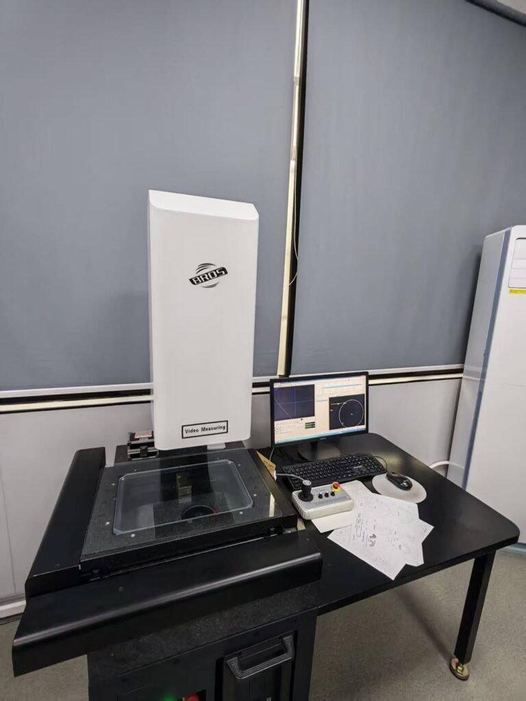
- Concentricity of the conducting path and outer geometry
- Flatness on substrate faces
- Surface roughness where metallisation or bonding follows
- Visual inspection for cracks and surface contamination
Parts made here, on our own equipment
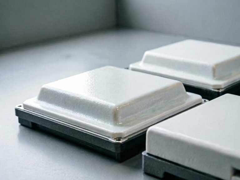
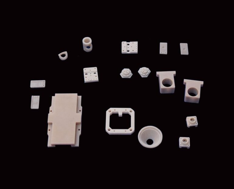
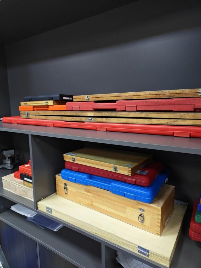
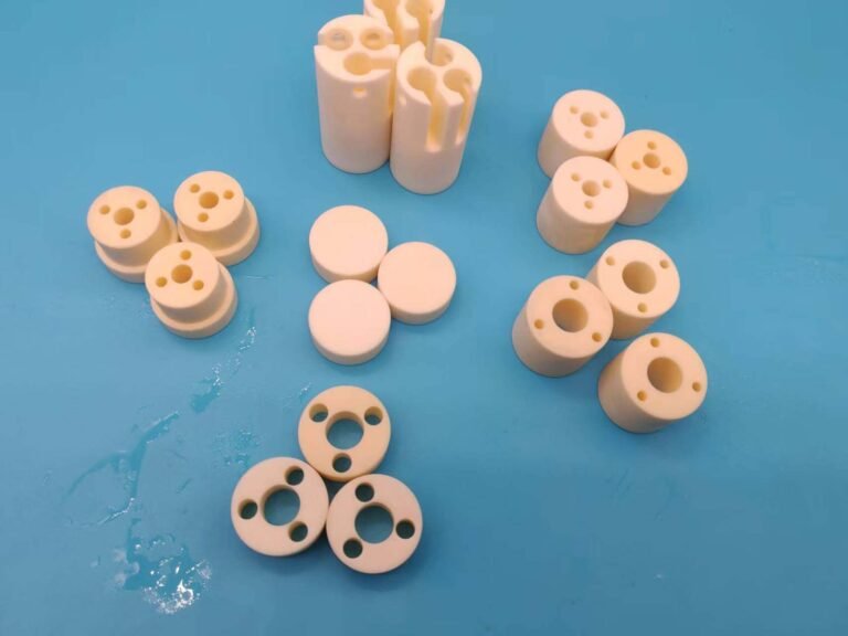
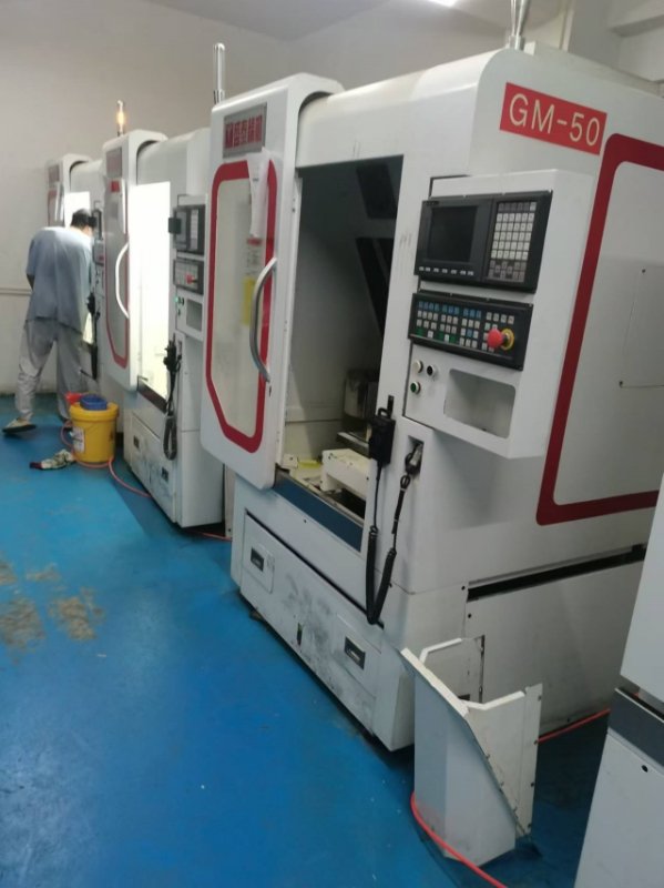
Component photographs are of parts produced in this factory. Equipment photographs are of this plant. No stock photography of facilities we do not own appears on this site.
What to send with a drawing
The review confirms material, route and inspection method from these inputs. Sending them with the drawing is what makes the first quotation accurate.
- Drawing or 3D model with creepage, clearance and wall thickness stated
- Material or grade if already specified; otherwise the voltage class, the heat flux and the cycling profile
- Flatness and mounting-hole position tolerances
- Quantity at each stage: evaluation, pilot and production
- Surface finish where metallisation or bonding follows; the substrate is supplied to the finish the coating process requires
- Inspection and documentation needs: dimensional report, material certificate
The part and the process
Frequently asked
Do you supply a voltage rating with an insulating part?
No. Parts are supplied to dimension and material specification. Dielectric performance depends on the assembly geometry, clearances and contamination level, and it is verified by the equipment builder.
Which ceramic for a power module substrate?
Aluminum nitride where heat has to pass through the insulator. Alumina is used where the heat flux is lower and cost matters more.
Can the surface be prepared for metallisation?
The substrate can be supplied with the surface finish and cleanliness the coating process requires. The coating itself is normally applied by a specialist process.
Send a drawing for this industry
State the equipment, the operating conditions and the quantities. The review confirms material and route before quoting. Initial engineering feedback is returned within 2 business hours during published business hours (Mon-Fri 9:00-18:00 GMT+8), excluding Chinese statutory holidays and company-announced non-working days; this is initial feedback on the drawing, not completion of a formal quotation or a full engineering review.