Manufacturing capability
Ceramic Micro Machining: Micro Holes and Narrow Slots
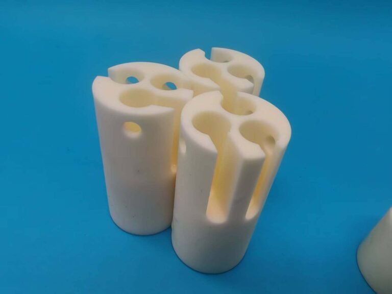
Micro features in technical ceramics, where feature size rather than overall part size defines the manufacturing difficulty.
Capability
Micro-feature capability
Figures below are the capability the shop is measured on. They are feature-specific, not a general tolerance.
Capabilities depend on material, geometry, feature size and finishing requirements. Critical dimensions are reviewed against the drawing.
Small features in hard material
Micro machining on ceramic is limited by tool stiffness and by edge chipping, not by the machine’s positioning resolution.
| Feature | How it is produced | Constraint |
|---|---|---|
| Minimum slot width | Down to 0.2 mm | Tool diameter sets the floor |
| Micro holes | Diamond micro drilling | Aspect ratio and entry angle |
| Micro holes below the tool range | Femtosecond laser drilling | Depth-to-diameter ratio and wall taper |
| Thin walls | Sub-millimetre sections | Support during machining |
| Micro pockets | Feasible with fine tooling | Depth-to-width ratio |
| Edge quality | Chipping risk rises as features shrink | Edge break specification |
Why micro features need a different plan
Tool deflection and heat concentration scale badly as feature size falls, so the sequence changes completely compared with a larger part in the same material.
- Shallow passes and reduced feed to control edge chipping
- Tool entry planned to avoid breakout on unsupported edges
- Feature order arranged so each one is still supported
- Coolant and cleaning planned around the small features
- Measurement method agreed before machining, not after
Measuring features this small
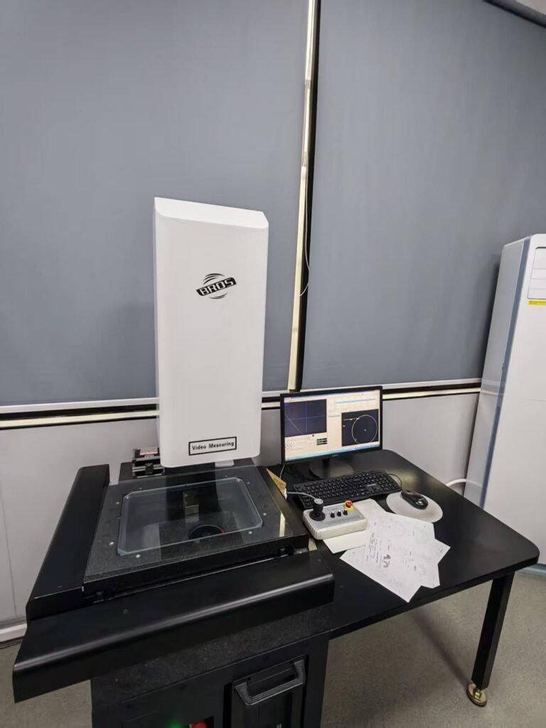
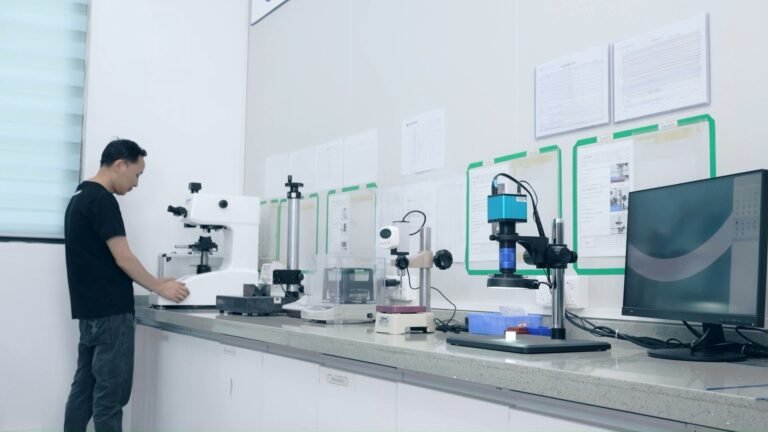
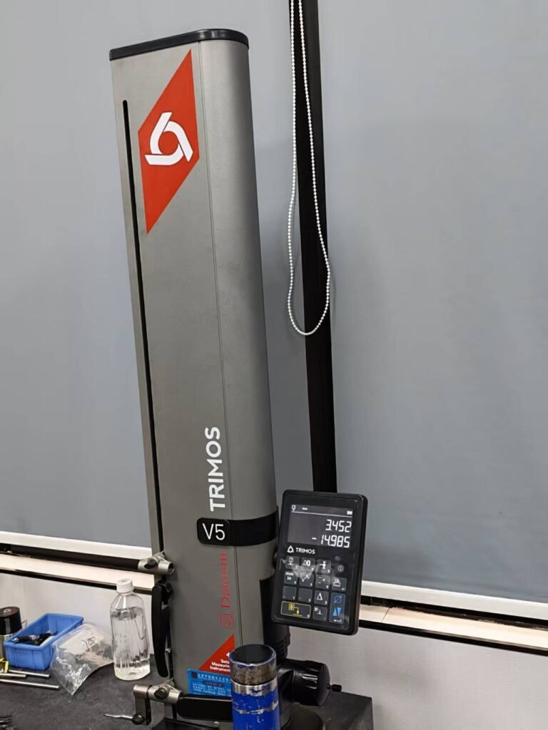
Optical and video measurement is used rather than contact probing, which cannot enter these features without risk.
Findings that are specific to micro features
At this scale the limit is rarely the machine. It is the tool, the entry edge and the wall left standing beside the feature. These are the findings that come back from review on parts this small.
| Finding | Why it happens | What helps on the drawing |
|---|---|---|
| Micro hole with a tight position tolerance | Entry angle and tool drift dominate at this scale, not the positioning resolution of the machine | Tolerate the position relative to the nearest datum feature rather than to a distant face |
| Aspect ratio beyond the tool range | The drill cannot clear chips, so the hole wanders and the edge breaks out at the far side | State the aspect ratio. Above the tool limit the route changes to laser drilling, which is quoted differently |
| Sharp entry edge on a micro hole | The edge chips on entry, and the chip is larger than the feature itself | Specify a chamfer, or accept an agreed edge criterion |
| Slot width set at the tool limit | The tool diameter sets the floor, so tool wear is inside the tolerance rather than outside it | Set the width and accept the tolerance the tool can hold, rather than the reverse |
| Thin wall between two micro features | The wall deflects during machining and again during measurement | Increase the wall where the function allows, or accept a looser tolerance and a measurement fixture |
| Surface finish specified inside a micro feature | The instrument has to reach the feature, which is not always possible | State the finish only where it is functional and reachable |
Femtosecond laser drilling for micro holes
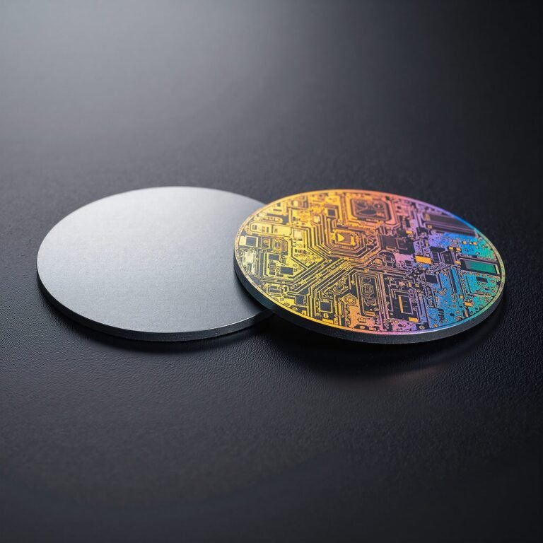
Korecera operates in-house femtosecond laser processing equipment for selected precision ceramic micro-feature applications. Feasibility depends on material, geometry, thickness and feature requirements. Where a hole is too small, too deep or too hard for a diamond tool to survive the cut, the material is removed by an ultrashort-pulse laser instead. Ultrashort-pulse laser processing can reduce the heat-affected zone relative to longer-pulse laser processes, but taper, recast, microstructure effects, edge condition and subsurface damage remain process- and material-dependent.
| Consideration | Femtosecond laser | Diamond drilling |
|---|---|---|
| Material hardness | Less dependent on conventional cutting-tool hardness limits; absorption, composition, thickness and feature geometry still affect process capability | Tool wear rises sharply with hardness |
| Heat input | Reduced heat-affected zone relative to longer-pulse laser processes; the remaining thermal and microstructural effects depend on parameters and material | Mechanical cutting, with coolant controlling the temperature |
| Very small diameters | Reaches sizes below the practical tool range | Limited by the smallest tool that survives the cut |
| Deep, small holes | Achievable at depth-to-diameter ratios a drill cannot hold | Aspect ratio limited by tool stiffness and swarf removal |
| Wall condition | Taper and wall finish are process-dependent and are stated after review | Straight wall with a ground finish |
| Typical application | Few difficult holes, or holes in the hardest grades | Any hole the tool can drill economically |
The part and the process
Frequently asked
What is the smallest slot you can produce?
The confirmed minimum slot width is 0.2 mm. Whether it is achievable on a given part depends on depth, material and how close the slot sits to an edge.
Do you machine micro holes with a laser?
Yes. Micro holes below the practical diamond-tool range, and holes in the hardest grades such as silicon carbide or silicon nitride, are produced on our in-house femtosecond laser processing equipment within the quoted process route. Hole diameter, depth, acceptable taper and edge condition are agreed from the drawing before production, because those items – not the laser alone – decide what the process can hold.
Can micro features be measured on a CMM?
Contact probing is not suitable for the smallest features. Video and optical measurement is used, and the method is agreed with you before production because it defines what the report can show.
Do micro features change the material recommendation?
Sometimes. A material that is fine for a large part can chip excessively at micro scale, so the selection may move towards a finer-grain grade.
How do I specify edge quality?
State the maximum acceptable edge chip or break, or reference an edge-break requirement. An unspecified edge is the most common cause of disagreement on micro-machined parts.
Send us the drawing and the requirement
We review manufacturability, tolerance and inspection method before quoting.